
A CEMS (Continuous Emissions Monitoring System) measures flue gas pollutants in real time. See how smart transmitters feed into CEMS-type systems.
Regulators require CEMS data for compliance with air quality limits for SO2, NOx, CO, CO2, O2, and particulate matter.
This guide covers CEMS components, extractive vs in situ types, calibration procedures, and DAHS data handling.
A CEMS is not a single instrument. It is a system of components working together: a sample probe, heated sample line, conditioning unit, gas analyzers, flow monitor, and a Data Acquisition and Handling System (DAHS) that validates and reports the results.
CEMS Explained: Why Continuous Emissions Monitoring Is Required
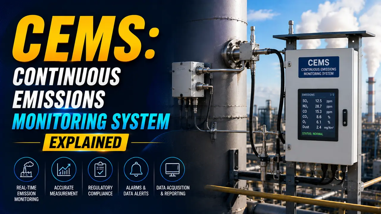
Environmental regulations require industries to prove their emissions stay within permitted limits, every hour of every day. A once-a-week stack test is not enough. A CEMS provides the continuous, validated data stream that regulators accept as proof of compliance.
The three core measurement tasks in a CEMS are: measuring pollutant gas concentrations, measuring stack gas flow rate, and running the DAHS (Data Acquisition and Handling System) that converts raw analyzer outputs into reportable emission rates. Click any term to expand.
CEMS Components: What Each Part Does
| Component | Function | Key Specification |
|---|---|---|
| Sample Probe | Extracts flue gas from the stack. Heated to prevent condensation and filter particulates before they reach the analyzer. | 316 SS or ceramic. Heated to 180°C minimum. In stack filter typically 2 to 5 micron. |
| Heated Sample Line | Transports the gas sample from the probe to the analyzer shelter without condensation. Condensation would dissolve SO2 and HCl, causing low readings. | Maintained at 180°C. Trace heated PTFE or SS tubing. Maximum 50 m run typical. |
| Sample Conditioning Unit | Removes moisture from the sample using a chiller (cooled to 4°C) or Nafion dryer. Dry basis measurement avoids interference from water vapor. | Peltier chiller to 4°C. Condensate trap and peristaltic drain pump. Sample pressure regulator. |
| Gas Analyzers | Measure each pollutant concentration. NDIR for SO2, CO, CO2. Chemiluminescence for NOx. Paramagnetic or electrochemical for O2. | Range: 0 to 2,000 ppm SO2, 0 to 1,000 ppm NOx. Linearity within 1% of full scale required. |
| Stack Flow Monitor | Measures gas velocity in the stack for mass emission rate calculation. Pitot array or ultrasonic type. | Differential pressure: 0 to 2,500 Pa typical. Ultrasonic: bidirectional, suitable for swirling flow. |
| Calibration Gas System | Injects certified reference gases at known concentrations for zero and span checks. Automated by a solenoid valve sequencer controlled by the DAHS. | Zero gas: nitrogen or CO2-free air. Span gas: traceable certified cylinders at 50 to 80% of full scale. |
| DAHS | Collects, validates, stores, and reports all analyzer data. Applies calibration correction factors. Generates regulatory reports. | Stores minute-level data. Calculates 15-minute, hourly, and daily averages. Audit trail protected. |
Extractive CEMS vs In Situ CEMS
There are two fundamentally different ways to measure stack emissions. The choice depends on the pollutant, the stack conditions, and the maintenance resources available.
Extractive CEMS
The gas sample is physically withdrawn from the stack, conditioned (dried and filtered), and brought to an analyzer in a shelter away from the stack. This is the most common configuration for SO2, NOx, and CO.
Advantages: Analyzers in a controlled environment. Easy maintenance. Single analyzer can measure multiple gases.
Limitations: Heated lines and conditioning system add cost and failure points. Moisture removal means measurement is on a dry basis -- must convert back to wet basis for reporting.
In Situ CEMS
The analyzer is mounted directly on the stack and measures the gas in place without extraction. Cross stack laser systems (DOAS or TDLAS) send a beam across the duct and measure absorption.
Advantages: No sample line or conditioner. Wet basis measurement directly. Suitable for sticky gases like HF and HCl that dissolve in condensate.
Limitations: Analyzer exposed to harsh stack conditions. Optical path length must be known. Difficult to service without plant shutdown.
CEMS Calibration: Zero, Span and Linearity Checks
CEMS calibration is not optional and not just a good practice. Regulations specify the frequency, acceptance criteria, and corrective action required when a check fails. Most regulations (US EPA 40 CFR Part 60, EU IED) require at minimum a daily automated zero and span check.
Zero Check
A zero gas (nitrogen or certified zero air) is injected. The reading must be within 2.5% of full scale. If it drifts beyond this, the DAHS flags the period and applies substitution data while recalibration is performed.
Span Check
A certified span gas (50 to 80% of full scale) is injected. The reading must be within 5% of the certified value. The DAHS calculates a calibration correction factor (CCF) applied to all subsequent readings. See the correction factor guide.
Linearity Check (Quarterly)
Three certified concentrations (20%, 50%, and 80% of span) are injected in sequence. The analyzer response must be within 5% of each certified value, confirming linearity across the full operating range.
CEMS Emission Rate Calculator
Where CEMS Is Required
Power Generation
Coal, gas, and oil-fired power stations are the largest regulated sources. SO2, NOx, CO2, and opacity CEMS are standard. Emissions trading schemes (EU ETS, US RGGI) depend entirely on CEMS data for allowance accounting. See the gas analyzers guide for analyzer types used.
Cement and Lime Kilns
Cement kilns produce high NOx from the very high flame temperatures and SO2 from sulfur in raw materials. NOx, SO2, HCl, HF, dust, and CO are all monitored. The EU Industrial Emissions Directive (IED) mandates continuous monitoring for installations above threshold capacity.
Waste Incineration
Waste incinerators have the strictest CEMS requirements. SO2, NOx, HCl, HF, CO, TOC, and dust must all be continuously monitored.
See the hazardous area guide for area classification near incinerator stacks.
Oil Refinery and Petrochemical
Refinery heaters, catalytic cracker regenerators, and sulfur recovery units require SO2 and NOx CEMS. Some jurisdictions also require continuous VOC and H2S monitoring at flare stacks. The explosion-proof instruments guide covers how analyzers are certified for hazardous areas near refinery stacks.
Watch: What Is a Continuous Emissions Monitoring System (CEMS)?
CEMS Questions Engineers Often Ask
External References
- EPA EMC: Continuous Emission Monitoring Systems -- Performance Specifications and Methods
- Introduction to CEMS -- CODEL International (updated 2025)
What We Learn Today
- A CEMS is a complete system: sample probe, heated line, conditioning unit, analyzers, flow monitor, calibration gas system, and DAHS
- Extractive CEMS dries the sample before analysis (dry basis). In situ CEMS measures across the stack directly (wet basis). Both have regulatory acceptance.
- CEMS must perform automated zero and span checks at least twice daily using certified reference gases traceable to national standards
- A failed calibration check triggers data substitution in the DAHS -- the 90th percentile of recent valid data replaces flagged hours, penalising poor maintenance
- Mass emission rate (kg/hr) = concentration (mg/Nm3) × stack flow (Nm3/hr) / 1,000,000 -- with O2 correction to a reference percentage
- Major regulated sources include power stations, cement kilns, waste incinerators, and oil refinery process heaters