Every PLC, microcontroller and ADC stores negative numbers the same way, and once you see the trick it never feels strange again. We walk through the method, the ranges, subtraction and overflow with worked binary examples.
2's complement is the standard way digital systems store signed whole numbers, so that one adder circuit can both add and subtract. This guide shows how to find it, how to read it and where it appears in PLC and SCADA work.

What Is 2's Complement?
2's complement is a binary method for writing negative numbers in which the most significant bit has a negative weight, so a pattern starting with 1 is negative. To find the 2's complement of a number you invert every bit and add one, which gives the negative of the original value.
- Rule: invert all bits, then add 1
- 8 bit range: minus 128 to 127, 16 bit range: minus 32768 to 32767
- MSB = 1 means the number is negative
- Subtraction A minus B is done as A + (minus B)
- Overflow happens when two numbers of the same sign give a result of the other sign
Before this method, designers tried sign magnitude and 1's complement, which both have two zeros and need extra logic to add. Our page on number systems covers plain binary, which you should be comfortable with before going further.
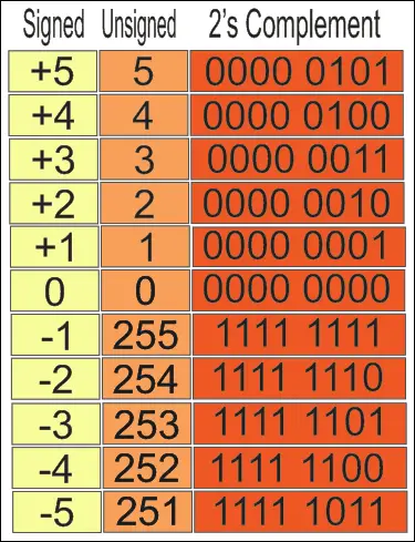
The table shows the key idea: the same 8 bit pattern 1111 1111 is 255 when read as unsigned and minus 1 when read as signed. The bits do not change, only the meaning we give to the top bit changes.
Cornell University course notes point out that the most negative value has no positive partner. In 4 bits you can write minus 8 but not plus 8, because the positive side stops at 7.
How to Find 2's Complement of a Binary Number
The method needs only two operations that any logic circuit can do quickly. First write the number with the full bit width you will use, because the leading zeros matter.
Invert = 1111 1010
Add 1 = 1111 1011
minus 5 = 1111 1011 (hex FB)
A faster hand method also works: copy the bits from the right up to and including the first 1, then invert all the bits to its left. For 0010 1000 this gives 1101 1000 in one pass, which is minus 40.
Applying invert and add one twice brings you back to the original number. Use it to check your answer during an exam or while decoding a register by hand.
Signed Binary Formula and Range
In an n bit signed number the top bit has the weight minus 2^(n minus 1), and every other bit keeps its normal positive weight. Adding the weights of the bits that are 1 gives the signed value directly.
1101 0011 = minus 128 + 64 + 16 + 2 + 1
1101 0011 = minus 45
Cornell gives the general range as minus 2^(N minus 1) up to 2^(N minus 1) minus 1 for N bits. The table lists the widths you will meet in PLC, microcontroller and SCADA work.
| Bits | Lowest value | Highest value | PLC type (IEC 61131 3) |
|---|---|---|---|
| 4 | minus 8 | 7 | Nibble |
| 8 | minus 128 | 127 | SINT |
| 16 | minus 32768 | 32767 | INT |
| 32 | minus 2147483648 | 2147483647 | DINT |
These are the same signed types described in PLC data types, and the unsigned forms USINT, UINT and UDINT simply read the top bit as a positive weight. Mixing the two is a common source of strange readings, as you will see below.
1's Complement vs 2's Complement
1's complement only inverts the bits, while the newer method inverts and adds one. That small extra step removes the second zero and lets a plain adder give correct signed results.
| Decimal | Sign magnitude | 1's complement | Invert plus one |
|---|---|---|---|
| plus 3 | 0011 | 0011 | 0011 |
| minus 3 | 1011 | 1100 | 1101 |
| plus 0 | 0000 | 0000 | 0000 |
| minus 0 | 1000 | 1111 | not needed |
| minus 8 | not possible | not possible | 1000 |
- Only one zero, so comparisons are simple
- The same adder does addition and subtraction
- Range is one value wider on the negative side
- Sign is read from the top bit directly
- Range is not symmetric
- Overflow gives a wrong sign silently
- Readers must know the bit width
- Signed and unsigned views can be confused
Binary Subtraction Using 2's Complement
Cornell puts it simply: subtraction is adding, where one operand is negated. To find A minus B you add A to the 2's complement of B and drop any carry out of the top bit.
25 = 0001 1001
13 = 0000 1101, so minus 13 = 1111 0011
0001 1001 + 1111 0011 = 1 0000 1100
Drop carry: 0000 1100 = 12
When the answer is negative there is no carry, and the result already sits in signed form. For 13 minus 25 the sum is 1111 0100, and inverting plus one gives 0000 1100, so the answer is minus 12.
minus 25 = 1110 0111
0000 1101 + 1110 0111 = 1111 0100
1111 0100 = minus 12
In hardware, the University of Hamburg Hades demo shows a 4 bit adder subtractor where XOR gates invert the B inputs and the carry in is set to 1 for subtraction. This is the same block found inside every ALU, built from the gates in digital logic gates.
NPTEL course notes describe the same trick: A plus the 1's complement of B plus 1 equals A minus B. One mode line chooses between adding and subtracting, so no separate subtractor circuit is needed.
Overflow in 2's Complement Addition
Overflow means the true result does not fit in the available bits. Cornell gives the rule that overflow occurs when both operands have the same sign but the result has the other sign.
0110 0100 + 0011 0010 = 1001 0110
Two positives gave a negative
Result reads minus 106, overflow
Adding a positive and a negative number can never overflow, because the result always lies between the two. Hardware flags overflow when the carry into the top bit differs from the carry out of it, and PLC math instructions set a status bit when it happens.
2's Complement in PLC INT Values and Modbus
A PLC INT is a 16 bit 2's complement number, so its range is minus 32768 to 32767. A raw value of hex FF38 therefore means minus 200, because FF38 is 65336 and 65336 minus 65536 gives minus 200.
Modbus holding registers are just 16 bit words with no sign attached, as explained in Modbus function codes. If the SCADA tag is set as unsigned, a temperature of minus 200 tenths of a degree shows up as 65336, so always match the data type at both ends.
| Symptom | Likely cause | Fix |
|---|---|---|
| Reading jumps to about 65000 near zero | Signed value read as unsigned | Set the tag type to INT, not UINT |
| Counter goes from 32767 to minus 32768 | INT overflow | Use DINT or reset the counter earlier |
| Analog value negative when sensor is fine | Under range or wiring fault shown as a negative count | Check the loop and scaling limits |
| Large value wrong after a move | DINT moved into INT and cut | Use the right conversion instruction |
Analog cards also report signed counts, and Siemens modules use 0 to 27648 for the nominal range, as covered in PLC analog scaling and raw count. Readings below the range show as negative INT values, which helps you detect an open loop.
2's Complement Calculator
Enter any whole number and a bit width, and the calculator shows the signed pattern in groups of four bits with its hex and unsigned value. Use a minus sign in the box for negative numbers.
The default shows minus 45, which matches the formula example above: 1101 0011 adds up to minus 128 + 83. Try 16 bits with minus 200 and you will get hex FF38, the same value from the PLC section.
See how a processor handles these numbers in microcontroller working principle, and how a bipolar input becomes a code in analog to digital conversion. Other binary codes worth knowing are BCD and Gray code.
- Bit width fixed before converting
- All bits inverted, then 1 added
- Top bit checked for the sign
- Carry out dropped after subtraction
- Overflow checked when both signs match
- Signed or unsigned type matched in PLC and SCADA
When a value looks wrong by exactly 65536 or 256, think of a signed and unsigned mix up first. It is far more common in the field than a faulty transmitter.
Try the PLC raw count calculator with a negative input to see the signed count. Then test the same value in a free simulator to watch the bits change live.
The Cornell slides also show how the adder hardware is built, which connects nicely to flip flop types when you move on to registers.
2's Complement FAQ
Write the number in binary with the full bit width, then invert every bit so each 0 becomes 1 and each 1 becomes 0. Add one to that inverted value and the result is the 2's complement.
For example, 5 in 8 bits is 0000 0101, inverting gives 1111 1010 and adding one gives 1111 1011. This pattern is minus 5 and the method works for any width.
In 4 bits, inverting 1010 gives 0101 and adding one gives 0110. So the 2's complement of 1010 is 0110, which is plus 6.
Read as a signed 4 bit number, 1010 itself is minus 6, because its top bit has the weight minus 8. Inverting and adding one has simply changed the sign of the value from minus 6 to plus 6.
It lets one adder circuit handle both addition and subtraction, since A minus B becomes A plus the negated value of the second number. It also has only one zero, which keeps comparisons and logic simple.
Sign magnitude and 1's complement both have a plus zero and a minus zero. They need extra correction steps, so almost every processor and PLC uses 2's complement today.
The 1's complement only inverts every bit of the number. The 2's complement inverts every bit and then adds one, so it is always one more than the 1's complement.
Because of that extra one, 2's complement has a single zero and a range one value wider on the negative side. It is the form used for signed integers in hardware.
Look at the most significant bit, which is the leftmost bit of the full width. If it is 1 the number is negative, and if it is 0 the number is zero or positive.
To find the size of a negative value, invert it and add one again and read the result as a normal binary number. Then put a minus sign in front of the answer.
A 16 bit signed integer in 2's complement runs from minus 32768 up to 32767. That is the INT type used in most PLC programs and Modbus based systems.
Going one count above 32767 wraps the value round to minus 32768. If your counter or total can grow beyond that limit, choose a 32 bit DINT with a far larger range instead.
Related Articles
- Introduction to Number Systems
- 9 PLC Data Types
- Arithmetic Logic Unit Architecture
- BCD Binary Coded Decimal
- Gray Code Binary Conversion
External References
- Cornell CS 3410: Numbers and Arithmetic (PDF)
- University of Hamburg Hades: Adder subtractor demo
- Wikipedia: Two's complement
What We Learn Today
- To find the 2's complement of any binary number you invert every bit and add one, and doing it twice returns the original value.
- An n bit signed number runs from minus 2^(n minus 1) to 2^(n minus 1) minus 1, so a 16 bit INT covers minus 32768 to 32767.
- Subtraction is just addition of a negated value, and overflow shows up when two numbers of the same sign produce a result of the opposite sign.