Thermocouple Transmitter Configuration: 4-20 mA Ranging and HART Setup

Share:
Temperature Measurement
Thermocouple Transmitter Configuration: 4-20 mA Ranging and HART Setup

A thermocouple transmitter has several parameters that are specific to thermocouple sensors and are not present when the same transmitter is configured for an RTD input.

Getting these parameters right

sensor type code, cold junction compensation mode, and burnout direction is the difference between a reliable loop and one that fails silently.

TC Type Selection Cold Junction Compensation Burnout Direction LRV and URV HART Setup

A thermocouple transmitter with the wrong TC type produces errors of 10 to 50 degrees C across the range.

No output trimming can fix this. The sensor type must match the physical thermocouple.

Hello everyone, today we are going to learn about thermocouple transmitter configuration including 4-20 mA ranging and HART setup.

We will cover the thermocouple-specific parameters you need to configure: sensor type selection, cold junction compensation, burnout direction, LRV and URV entry, and the HART secondary variable assignment for thermocouple loops.
We will also include a step-by-step configuration sequence, worked examples, common mistakes, and a comparison table of thermocouple type codes and their temperature ranges.
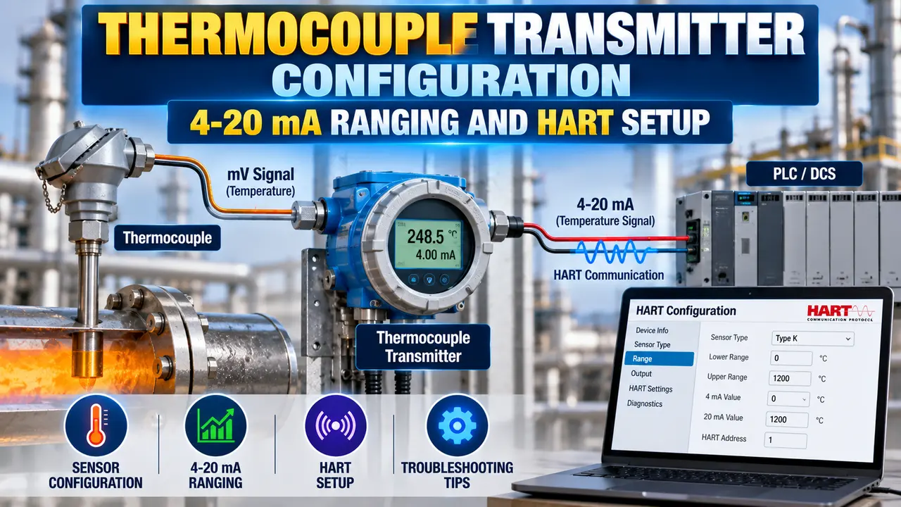
thermocouple transmitter

Why Thermocouple Transmitter Configuration Differs from RTD

A thermocouple generates a small millivolt signal from the temperature difference between the measuring junction and the reference junction at the transmitter terminals.

The reference junction at the terminals is called the cold junction.

An RTD transmitter measures resistance. A thermocouple transmitter must also linearise the millivolt input against the TC characteristic curve and add cold junction compensation for the terminal temperature.

These three differences create several transmitter parameters that are unique to thermocouple configuration and do not appear in RTD setup menus.

Advertisement

Thermocouple Type Selection: Codes and Temperature Ranges

The first and most critical configuration parameter is the thermocouple type. Each type code uses a different characteristic curve to convert millivolt input into a temperature value.

If the wrong type is selected, the transmitter linearises against the wrong curve. The error is non-linear and changes across the range. The only fix is to configure the correct TC type.

TC TypeMetal PairTypical RangeCommon Applications
Type KNickel-Chromium / Nickel-Aluminiumminus 200 to 1260 degrees CMost common general-purpose TC. Used widely in process plants, kilns, and heat treatment.
Type JIron / Copper-Nickelminus 40 to 750 degrees COlder installations, lower-temperature oxidising and reducing atmospheres. Being phased out in new designs.
Type TCopper / Copper-Nickelminus 200 to 350 degrees CCryogenic service, food and pharma cold applications, refrigeration.
Type ENickel-Chromium / Copper-Nickelminus 200 to 900 degrees CHighest EMF output per degree of all common types. Used where sensitivity is important.
Type NNickel-Chromium-Silicon / Nickel-Siliconminus 200 to 1300 degrees CHigh-temperature service with improved drift stability compared to Type K.
Type SPlatinum-10% Rhodium / Platinum0 to 1450 degrees CHigh-accuracy high-temperature service: steel, glass, ceramics. Used as a calibration reference.
Type RPlatinum-13% Rhodium / Platinum0 to 1450 degrees CSame applications as Type S. Slightly higher EMF output. Used in high-temperature furnaces.
Type BPlatinum-30% Rhodium / Platinum-6% Rhodium600 to 1700 degrees CVery high temperature service only. Output is extremely low below 600 degrees C. Do not use below this range.
How to verify the TC type installed on site: Check the thermocouple head terminal block. The thermocouple manufacturer marks the TC type on the element or on the head terminal strip. If unmarked, check the instrument datasheet or loop drawing. If still unknown, use a TC identifier tool that measures the millivolt output at a known temperature and matches it to the correct curve. Never guess the TC type based on the wire colour alone colour coding varies by country and standard (IEC 60584 vs ANSI vs BS). See the thermocouple polarity identification guide for colour coding details by standard.

Cold Junction Compensation: Modes and Error Sources

A thermocouple measures the temperature difference between its measuring junction and its cold junction. The cold junction is where the thermocouple wires terminate at the transmitter input terminals.

The transmitter must know the temperature at its own terminals to calculate the absolute process temperature. This measurement and correction is called cold junction compensation (CJC).

CJC Modes Available in Most Transmitters

Internal CJC
The transmitter contains a small temperature sensor (usually a thermistor or thin-film platinum element) mounted close to the input terminals. This sensor measures the local terminal temperature and the transmitter adds this value to the thermocouple millivolt reading automatically. Typical accuracy: plus or minus 0.5 to 1.0 degrees C. Used in the vast majority of industrial installations.
External CJC
A dedicated external RTD (usually Pt100) is mounted at the thermocouple terminal block and connected to the transmitter as a separate input. This gives better CJC accuracy (typically plus or minus 0.1 to 0.3 degrees C) because the RTD is located exactly at the cold junction, not inside the transmitter electronics. Used for high-accuracy thermocouple measurements in laboratory and calibration service.
Fixed CJC value
A fixed temperature value (such as 0 degrees C) is entered as the cold junction reference. The transmitter does not measure the actual terminal temperature. This mode is used in ice-point reference cells (the terminal block is kept at exactly 0 degrees C by a controlled ice bath) and in some high-accuracy laboratory applications. Not suitable for field installation where the terminal temperature varies with ambient.
Common CJC error cause: Mounting the transmitter in a hot location (inside an unventilated cabinet, near a hot pipe, or in direct sunlight) causes the terminal temperature to rise significantly above ambient. The internal CJC sensor measures this elevated temperature but cannot correct for rapid fluctuations caused by hot air currents hitting the input terminals intermittently. This produces a fluctuating temperature reading that the DCS operator sees as a noisy or unstable measurement. Always mount a thermocouple transmitter in a location where the terminal temperature is stable and as close to the ambient temperature of the surrounding environment as possible.
Advertisement

Burnout Direction: Upscale vs Downscale

A thermocouple generates no voltage when the wire breaks. The transmitter detects this open-circuit and drives its output to a predefined level. This is called the burnout or sensor failure response.

The burnout direction determines whether the transmitter drives its output to a high value or a low value when a wire break is detected.

Upscale burnout
The transmitter drives its output to 21.0 to 21.6 mA on sensor failure. This value is above the 20 mA full-scale limit of the normal signal range. The DCS reads this as an over-range condition and triggers a sensor failure alarm. Used when a high temperature alarm is the safer fail-state for the process.
Downscale burnout
The transmitter drives its output to 3.6 to 3.8 mA on sensor failure. This value is below the 4 mA live-zero level of the normal signal range. The DCS reads this as an under-range condition and triggers a sensor failure alarm. Used when a low temperature alarm is the safer fail-state, or when the process control action on a low reading is safer than on a high reading.
Burnout disabled
Not recommended for thermocouple service. If burnout detection is disabled and the thermocouple wire breaks, the transmitter may hold its last reading, output a mid-scale value, or behave unpredictably. The DCS receives what appears to be a valid signal. The control loop continues to act on meaningless feedback. Always enable burnout detection on thermocouple loops.
How to select the correct burnout direction: Ask two questions. First, what does the control loop do if it sees a high temperature reading? If it cuts heat supply or shuts down, then upscale burnout is safe the loop will shut down when the TC fails. Second, what does the loop do if it sees a low reading? If it adds heat, then upscale burnout is still safer. If the loop would add heat on a low reading, and adding heat during a TC failure is dangerous, use upscale burnout to prevent this. Discuss with the safety and process engineer before selecting. Document the selected burnout direction on the loop drawing and in the transmitter datasheet.

Setting LRV and URV for a Thermocouple Loop

The Lower Range Value (LRV) is the temperature that corresponds to 4 mA output. The Upper Range Value (URV) is the temperature that corresponds to 20 mA output.

The LRV and URV must both fall within the allowable range of the selected TC type. For Type K, this is minus 200 to 1260 degrees C.

Values outside this range are rejected or produce an error.

Range selection rule
Set the LRV and URV so that the normal operating temperature sits between 25% and 75% of the configured span. This gives the instrument meaningful resolution and leaves headroom above and below for process excursions without the output saturating at 4 or 20 mA.
Minimum span
Most transmitters specify a minimum configurable span. For a thermocouple input, this is typically 10 to 25 degrees C. Do not configure a span narrower than the minimum. The transmitter will either reject the entry or the signal noise will dominate the reading, producing an unstable output.
Re-ranging vs trimming
Changing the LRV and URV is re-ranging. It shifts the scale so the output represents a different temperature range. It does not correct the temperature accuracy. To correct the temperature reading against a reference, use sensor trim via HART. See the temperature transmitter calibration guide for the full sensor trim procedure.
Worked Example: Reactor Outlet Temperature
Process: Reactor outlet temperature, normal 280 degrees C, maximum 380 degrees C
TC type: Type K (selected to cover the full range with margin)
LRV: 150 degrees C (corresponds to 4 mA)
URV: 450 degrees C (corresponds to 20 mA)
Span: 300 degrees C
Normal operating point: 280 degrees C = 4 + (280 minus 150) divided by 300 x 16 = 10.93 mA
Burnout direction: Upscale (21 mA) because a false low reading would increase reactor heat input, which is dangerous
CJC mode: Internal (standard field installation)
Result: Normal operation sits at 44% of span. Alarm at 380 degrees C = 17.87 mA. Transmitter output goes to 21 mA if TC wire breaks.
Advertisement

HART Configuration: Step-by-Step for a Thermocouple Transmitter

HART communication allows the complete transmitter configuration to be read and written digitally using a HART communicator (such as the Emerson 475 or AMS Trex) connected anywhere on the 4-20 mA loop.

The minimum loop resistance for HART is 250 ohms. Most DCS input cards include a 250 ohm resistor. Verify the resistance before connecting on a live loop.

1
Connect the HART communicator in parallel with the transmitter terminals or across any convenient point on the 4-20 mA loop. Power the loop at 24 V DC. The communicator will poll for HART devices and display the transmitter tag and current configuration once communication is established.
2
Set the sensor type in the transmitter configuration menu. Select the correct thermocouple type: K, J, T, E, N, S, R, or B as appropriate. An incorrect selection will linearise the millivolt input against the wrong curve, producing a non-linear temperature error across the full range that cannot be corrected by output trimming.
3
Set the cold junction compensation mode: Select internal CJC for standard field installations. Select external CJC if an external Pt100 is wired to the transmitter CJC terminals. Select fixed value only if an external ice-point reference cell is used. Verify the CJC temperature displayed by the communicator matches the actual ambient temperature at the transmitter terminals.
4
Enter the LRV (temperature at 4 mA). This must be within the allowable range of the selected TC type. Confirm the value is correct before proceeding. On most transmitters, entering an out-of-range LRV produces an error; on some older models it may be accepted silently and produce an incorrect calibration.
5
Enter the URV (temperature at 20 mA). Verify the span (URV minus LRV) is greater than the transmitter's minimum configurable span. On most HART transmitters the communicator will show a confirmation message after URV entry. The output will immediately adjust to represent the new range.
6
Set the burnout direction in the sensor failure or error handling menu. Select upscale (21 mA) or downscale (3.6 mA) based on the process safety requirement. Verify the DCS alarm is configured to detect the selected burnout value as a sensor failure, not as a process temperature alarm.
7
Assign HART secondary variables. A HART thermocouple transmitter can transmit up to four digital variables: PV (primary variable, the temperature as 4-20 mA), SV (secondary variable), TV (third variable), and QV (fourth variable). Configure the SV as the transmitter terminal temperature (CJC value) so the DCS can monitor the cold junction temperature as a separate parameter. This allows the operator to detect CJC errors from the control room.
8
Set the damping value if the thermocouple is in a high-noise or high-vibration environment. A damping of 2 to 5 seconds is typical for most process temperature loops. Excessive damping slows the response to real temperature changes, so do not set it higher than the application requires.
9
Write the device tag (loop number, instrument tag from the datasheet) and the engineering units (degrees C or degrees F) via the HART communicator. These are used by the asset management system and appear in diagnostic reports. Verify the tag matches the P&ID tag number exactly.
10
Verify the output by checking the mA output at a known temperature. Place the process at a stable reference temperature (or simulate the TC input using a calibrator) and compare the transmitter output against the expected mA value from the configured LRV and URV. Any deviation beyond the transmitter's accuracy specification requires sensor trim, not re-ranging. See the temperature transmitter calibration guide for trim procedure.

Common Thermocouple Transmitter Configuration Mistakes

Wrong TC type selected
A transmitter configured for Type J but with a Type K sensor installed will read approximately 30 to 100 degrees C differently than the actual temperature, depending on the process temperature. This error is non-linear and cannot be corrected by any output adjustment. Verify the TC type on the sensor or the loop drawing before configuring.
Wrong extension cable
Using the wrong type of thermocouple extension cable between the sensor head and the transmitter introduces a millivolt error at every junction. A Type K sensor with Type J extension cable will produce a large, temperature-dependent error. See the extension cable vs compensating cable guide for the correct cable selection rules.
Reversed TC polarity
Connecting the thermocouple wires with reversed polarity causes the transmitter to drive its output in the wrong direction. At ambient temperature, the reading may be close to correct, but as process temperature rises, the output falls instead of rising. The error grows with temperature. Always verify polarity at the terminal block. See the polarity identification guide.
Burnout detection disabled
A thermocouple wire break with burnout detection disabled gives a frozen or mid-scale reading. The DCS sees a plausible temperature value and does not alarm. The control loop continues running with a meaningless feedback signal. Always enable burnout detection and verify the correct direction is selected before commissioning.
Output trim used instead of sensor trim
If the temperature reading is slightly off, the correct fix is sensor trim (which corrects the conversion from millivolt input to temperature) not output trim (which adjusts the 4-20 mA DAC output). Using output trim to correct a temperature error shifts the mA output but the transmitter's internal temperature value remains wrong. HART read-back of the primary variable still shows the uncorrected temperature. Use sensor trim for temperature errors and output trim only to correct the current output endpoint accuracy.

Watch: Thermocouple Transmitter HART 475 Calibration and Configuration

Advertisement

Thermocouple Transmitter Configuration Questions

Why does the TC type selection matter so much in a thermocouple transmitter?
Each thermocouple type has a different millivolt-to-temperature characteristic curve. The transmitter linearises the input using this curve. If the wrong TC type is selected, the error is non-linear and changes across the range. It cannot be fixed by trimming.
What is cold junction compensation in a thermocouple transmitter?
A thermocouple measures the temperature difference between the measuring junction and the cold junction at its terminals. Cold junction compensation adds the terminal temperature to the millivolt reading so the output is an absolute process temperature. Without it, the reading drifts with ambient.
What is the difference between upscale and downscale burnout in a thermocouple transmitter?
Upscale burnout drives the output to 21 mA on TC wire break. Downscale drives it to 3.6 mA. The DCS detects either as a sensor fault. The correct direction depends on which control loop response is safer when the sensor fails.
How does a HART communicator connect to a thermocouple transmitter loop?
The HART communicator connects in parallel across any two points on the 4-20 mA loop. At least 250 ohms must be present in the loop. Most DCS input cards include a 250 ohm resistor. Power the loop at 24 V DC before connecting.
What HART secondary variables are useful for a thermocouple transmitter?
Configure the SV as the transmitter terminal temperature (cold junction value). This allows the DCS to monitor CJC quality separately. An unstable SV indicates the transmitter is in a hot location and CJC is introducing errors into the temperature reading.

Related Articles on This Site

External References

What We Learn Today

  • TC type is the most critical step. A wrong TC type produces a non-linear error that cannot be corrected by trimming. CJC corrects for the terminal temperature so the output is an absolute process temperature.
  • Burnout direction is set based on the process safety requirement. Upscale (21 mA) or downscale (3.6 mA) drives the output out of range on TC wire break. Always enable burnout detection on thermocouple loops.
  • HART configuration covers sensor type, CJC mode, LRV, URV, burnout direction, SV assignment, damping, and device tag. Configure the SV as the terminal temperature to monitor CJC quality. Use sensor trim for temperature errors, not output trim.
I hope you like above blog. There is no cost associated in sharing the article in your social media. Thanks for reading!! Happy Learning!!

Leave a Reply

Your email address will not be published. Required fields are marked *