
A swirl flow meter spins the incoming fluid, lets the vortex core precess and counts that precession frequency to find the volume flow. It needs very short straight pipe, handles low gas flows well and suits cramped skids where a vortex meter will not fit.
The swirl principle turns flow into a clean frequency by forcing the fluid to rotate and precess inside a shaped meter body. This guide explains the physics, the installation rules, the K factor maths and how it compares with a vortex meter.
What Is a Swirl Flow Meter?
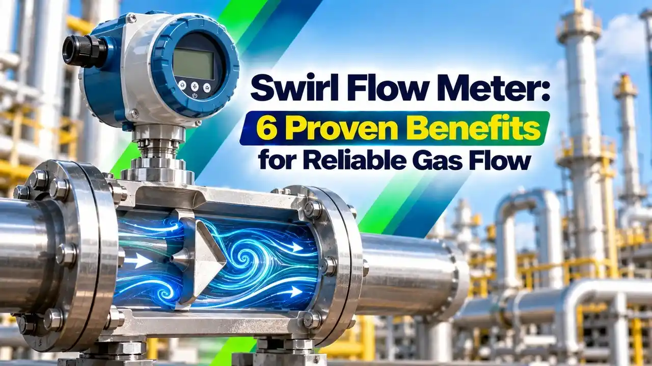
A swirl flow meter is a volumetric flowmeter that forces the fluid to rotate with a fixed inlet swirler and then measures how fast the core of that rotating flow precesses, or wobbles, around the pipe axis. The precession frequency is proportional to velocity, so the meter gives a pulse output just like a turbine flow meter, but without any moving parts.
It belongs to the family of oscillating flowmeters, alongside the vortex flow meter, and the two are often sold under one product line. The swirl version is also called a vortex precession meter in many Asian catalogues, where it is common for natural gas and compressed air.

How the Precession Principle Works Inside the Meter Body
At the inlet, a set of fixed blades turns axial flow into a rotating flow. When this rotating fluid passes a converging section and then enters a wider zone, a low pressure core forms on the axis and starts to move in a helical path.
ABB explains in its application note that the swirler creates tangential velocity that produces a low pressure zone, and the result is a secondary rotation proportional to flow rate. A piezoelectric sensor placed where the core sweeps past senses one pressure pulse per revolution of the precessing core.
At the outlet, a deswirler, which is a straightener with vanes, removes the rotation so the fluid leaves in a near axial pattern. This protects downstream instruments such as a differential pressure transmitter or a sampling point from swirl effects.
Volume flow Q = f ÷ K, where K is pulses per unit volume
St is a near constant Strouhal type number fixed by the meter geometry
d is a characteristic bore size of the meter body
A swirl flow meter has no rotating parts, yet its output is a pulse train like a turbine meter. The swirler and deswirler blades are fixed, so only the fluid moves.
Swirl Flow Meter vs Vortex Meter
The biggest practical difference is straight pipe. ABB lists, for a vortex meter, 15 diameters upstream after a reduction, 50 diameters after a control valve and 5 diameters downstream, while the swirl version needs only 3, 5 and 1 diameters for the same cases.
| Feature | Swirl Meter | Vortex Meter |
|---|---|---|
| Straight run after control valve | 5 D upstream | 50 D upstream |
| Straight run after reducer | 3 D upstream | 15 D upstream |
| Downstream run | 1 D | 5 D |
| Low flow ability | Very good | Moderate |
| Pressure loss | Higher | Lower |
| Typical sizes | Small to medium | Medium to large |
Sino Instrument notes that the swirl design has a Venturi like contraction and expansion, so its pressure loss is clearly higher than the straight bore of a vortex meter. It also notes that vortex meters perform best from about DN25 upwards, while swirl designs are favoured in small bores.
ABB also states that its swirl design can offer accuracy up to 0.5 percent, which is better than many vortex installations with poor straight runs. For broader background on the options, compare them in types of flow meters before you finalise the choice.
When a skid has a control valve, a bend and a reducer within two metres, check the swirl option first. It often removes the need to reroute the piping just to gain straight length.
6 Proven Benefits of a Swirl Flow Meter
Those six benefits explain why the swirl flow meter is popular on gas lines where a wide turndown is needed and pipe space is tight. They do not make it universal, because the higher pressure loss and the limit on dirty fluids still apply.
K Factor and Flow Calculation
Every meter is wet calibrated and supplied with a K factor in pulses per litre or pulses per cubic metre. The calculation is the same one used in flow meter K factor calculations for any pulse output instrument.
For gases, the actual flow at line conditions must be converted to normal or standard flow. The method follows the gas laws covered in actual flow, standard flow and normal flow, and uses absolute pressure and absolute temperature.
Normal flow: Qn = Q × (P + 1.01325) ÷ 1.01325 × 273.15 ÷ (273.15 + T)
f in Hz, K in pulses per m³, P in bar gauge, T in °C
Example:
f = 250 Hz, K = 9000 pulses per m³, P = 4 bar g, T = 40 °C
Q = 250 × 3600 ÷ 9000 = 100.00 m³/h
Pressure ratio = 5.01325 ÷ 1.01325 = 4.9477
Temperature ratio = 273.15 ÷ 313.15 = 0.8723
Qn = 100 × 4.9477 × 0.8723 = 431.57 Nm³/h
Swirl Flow Meter Calculator
In a plant, this conversion is done inside the transmitter or in a flow computer using live pressure and temperature. The details of compensation are explained in temperature and pressure compensation.
Second Worked Example: Saturated Steam Line
A swirl flow meter on a saturated steam header at 10 bar gauge shows an actual volume flow of 80 m³/h. Steam tables give a density of roughly 5.6 kg per m³ at this pressure, so mass flow is about 80 × 5.6 = 448 kg/h.
For saturated steam, a pressure or temperature input alone is enough to find density, because the two are linked. For superheated steam, both pressure and temperature must be measured, otherwise the mass flow can be wrong by several percent.
Many swirl meters for gas include a built in pressure sensor and a temperature sensor in the same body. The transmitter then reports normal flow directly without a separate flow computer.
Where to Use and Where to Avoid the Swirl Principle
Burner skids, city gas stations and furnace headers.
Compressor room headers and plant air audits.
Small boiler outlets and process heaters.
Water, solvents and low viscosity chemicals.
ZINACA Instruments lists sizes from DN15 to DN200 with accuracy classes of plus or minus 1.0 or 1.5 percent and a flow range ratio of about 15 to 20. For gas services where you want a mass reading instead, also consider a thermal mass flow meter.
Avoid a swirl flow meter for dirty, sticky or two phase fluids, because deposits on the swirler blades change the K factor. High viscosity liquids lower the Reynolds number and push the meter below its linear range, so check the minimum Reynolds limit in the datasheet.
Installation Steps for Accurate Readings
Reduce line size to the swirl flow meter size where flow is low, because a smaller meter gives a stronger signal. Pipe vibration can create false pulses, so support the pipe well, as also advised in vortex flow meter troubleshooting.
On steam service, mount the meter so that condensate cannot collect in the body during shutdown. Water hammer from trapped condensate can damage the sensor on restart.
Common Swirl Flow Meter Problems and Fixes
- Zero flow shows a reading: raise the low flow cut off or check vibration.
- Reading too low: look for deposits on the swirler blades.
- Unstable signal: check for pulsating flow from compressors.
- Normal flow wrong: verify pressure and temperature inputs.
- No output: confirm sensor cable and transmitter power.
- Drift after shutdown: inspect for trapped liquid in gas lines.
Pulsating flow from reciprocating compressors can lock onto the meter frequency and produce errors, so read measuring pulsating flow in industrial piping if the meter sits near such a machine. Other general causes are listed in factors affecting flow meter readings.
- Very short upstream and downstream straight pipe.
- Good response at low gas velocities.
- No moving parts and low maintenance.
- Linear pulse output with a fixed K factor.
- Handles gas, steam and clean liquids.
- Higher pressure loss than a vortex meter.
- Not suited to dirty, sticky or two phase fluids.
- Limited to small and medium line sizes.
- Sensitive to strong pipe vibration and pulsation.
- Needs minimum Reynolds number for linearity.
Selection Guide and Standards
Start the selection with the process data sheet: fluid, minimum, normal and maximum flow, pressure, temperature and allowable pressure drop. Then compare options with the help of how to select the right flow meter and confirm low end performance from flow meters for low flow applications.
For custody transfer of natural gas, check what your contract and local regulator accept, since many tariffs in India specify ultrasonic or turbine meters. The common choices are compared in types of natural gas flow meters.
ABB Swirl Versus Vortex Application Note
Vortex and Swirl Flowmeter Tutorial Video
Swirl Flow Meter FAQ
It is a volumetric meter that rotates the fluid with fixed inlet blades and measures the precession frequency of the vortex core. That frequency rises in direct proportion to the flow velocity.
The output is a pulse train that is scaled with a K factor into volume flow. Many models also convert it to normal flow using built in pressure and temperature sensors.
A vortex meter counts vortices shed alternately from a bluff body in a straight bore. The swirl design counts the wobble of a rotating core created by a swirler.
Because the flow is conditioned inside the body, the swirl type needs far less straight pipe. The trade off is a higher pressure loss due to its contraction and expansion shape.
ABB lists 3 diameters upstream after a reducer, 5 diameters after a control valve and 1 diameter downstream. A comparable vortex meter needs 15, 50 and 5 diameters for the same three cases.
Always follow the exact figures in the maker datasheet for your model. Bends in two planes and partly open valves are the most demanding upstream disturbances in real plants.
The deswirler is a set of fixed vanes at the outlet of the meter body. It removes the rotation that the inlet swirler gave to the fluid before it leaves the meter.
Without it, swirl would carry downstream and upset other instruments or sampling points. It also helps keep the flow pattern stable around the sensing area and the outlet flange.
Yes, many models are calibrated for saturated and superheated steam on small and medium lines. The transmitter then needs a pressure or temperature input to calculate steam density and mass flow.
For saturated steam one variable is enough, since pressure and temperature are linked. Superheated steam needs both live values for an accurate and repeatable mass reading.
Deposits on the swirler blades change the flow pattern and shift the K factor over time. Wet gas, trapped condensate, pulsation and pipe vibration are other common causes in the field.
Inspect and clean the swirler and sensor internals during planned plant shutdowns. Then compare the reading with a reference meter or a portable clamp on ultrasonic meter where possible.
Small and medium sizes suit it best, with ranges such as DN15 to DN200 in many catalogues. Large lines usually favour vortex or ultrasonic meters because pressure loss grows with size.
When flow is low, reducing to a smaller meter gives a stronger signal. Always check the extra pressure drop against the available line pressure.
Related Articles
- Vortex Flow Meter Working Principle
- Flow Meter K Factor Calculations
- Turndown Ratio in Flow Meters
- Temperature and Pressure Compensation
- Types of Natural Gas Flow Meters
External References
- Swirl versus Vortex Flowmeter Technology, ABB Application Note
- Detailed Comparison of Swirl and Vortex Flow Meters, Sino Instrument
- Flow Measurement, Wikipedia
What We Learn Today
- A swirl flow meter rotates the fluid with fixed blades and counts the precession frequency of the vortex core, which rises in proportion to flow.
- ABB lists only 3 diameters after a reducer and 5 after a control valve, against 15 and 50 diameters for a vortex meter.
- Volume flow equals frequency times 3600 divided by K factor, and normal flow then uses absolute pressure and temperature ratios.