What are communication protocols?
Communication protocols serve as a framework of rules enabling seamless data exchange and connection between electronic devices.
These protocols define the specific formats and rules for digital messages, facilitating effective communication between devices.
Whether it’s digital or analog communication, the presence of well-defined communication protocols is crucial for establishing reliable and efficient data transmission.
Types of communication protocols?
There are two types of communication protocols
- Inter System Protocol
- Intra System Protocol
Inter System Protocols
Inter System Protocol serves as a crucial means of communication between different devices, enabling efficient data exchange. It is particularly utilized in scenarios where seamless communication is required between devices of varying architectures, such as a computer and a microcontroller circuit.

There are different categories of Intersystem Protocols:
1. UART Communication Protocols – Universal Asynchronous Transmitter and Receiver
- UART is a popular serial communication protocol.
- It uses two wired protocols: Rx (receiver) and Tx (transmitter).
- UART operates in a half-duplex mode, allowing either data transmission or reception at a given time.
- Data is transmitted in the form of bytes, with each byte consisting of a start bit, 8 bits of data, and a stop bit.
- UART is commonly used for communication between devices like computers and microcontroller circuits.
- It is a reliable and widely supported communication protocol in the electronics industry.
2. USART Communication Protocols – Universal Synchronous and Asynchronous Transmitter and Receiver
- It is a versatile protocol that supports both synchronous and asynchronous modes of communication.
- USART combines the functionalities of both UART (Universal Asynchronous Receiver and Transmitter) and synchronous communication protocols.
- It offers enhanced capabilities compared to UART, such as the ability to synchronize data transmission with an external clock signal.
- USART supports full-duplex communication, allowing simultaneous transmission and reception of data.
- It provides flexible baud rate configurations to accommodate various data transfer speeds.
- USART is commonly used in applications requiring reliable and high-speed serial communication, such as in microcontrollers, embedded systems, and communication interfaces.
- With its compatibility with both synchronous and asynchronous modes, USART offers greater flexibility and versatility in data transmission.
3. USB Communication Protocols – Universal Serial Bus
- Two wired protocols: USB utilizes two data cable lines, namely D+ and D-, for communication between devices.
- Serial data transmission: It enables the sequential transmission of data from a host device to peripheral devices, allowing for efficient communication.
- Host and peripheral connectivity: USB is used to send data between the host device (e.g., computer) and peripheral devices such as mice, keyboards, printers, and more.
- Transfer modes: USB supports various modes of data transfer, including slow speed mode (10kbps to 100kbps), full speed mode (500kbps to 10mbps), and high-speed mode (2mbps to 400 Mbps). The transfer mode is determined by the specific requirements of the connected devices.
- Cable length limitations: USB has a maximum cable length of 4 meters, ensuring reliable data transmission within this range.
Intra System Protocols
The Intra System Protocol is specifically designed for facilitating communication between devices within the circuit board. Its primary function is to reduce circuit complexity, power consumption, and overall cost. It streamlines the data transfer process and ensures efficient operation of the system.
There are different categories of Inter System protocols.
1. I2C Protocol – Inter-Integrated Circuit Protocol
- The I2C (Inter-Integrated Circuit) protocol is a master-slave communication protocol.
- It uses two wires, SDA (Serial Data Line) and SCL (Serial Clock Line), for information exchange.
- SDA and SCL lines are bidirectional, allowing data transmission and reception.
- The master device initiates communication and controls the timing of data transfer.
- Slave devices respond to commands and provide data as requested.
- It enables efficient and reliable communication between multiple devices on the bus.
- I2C protocol reduces circuit complexity, power consumption, and cost.
- It provides secure access to data within the circuit board.
2. SPI Protocol – Serial Peripheral Interface Protocol
- SPI (Serial Peripheral Interface) is a serial communication protocol developed by Motorola.
- It is commonly referred to as a 4-wire protocol due to its four communication lines: MOSI (Master Out Slave In), MISO (Master In Slave Out), SS (Slave Select), and SCLK (Serial Clock).
- SPI is primarily used for communication between master and slave devices.
- It supports full-duplex communication, allowing simultaneous transmission and reception of data.
- Unlike some other protocols, SPI is not limited to transferring data in 8-bit words, providing flexibility for different data sizes.
- It offers high-speed data transfer rates and is commonly used for connecting peripherals such as sensors, displays, and memory devices.
- SPI enables efficient and reliable data exchange between devices, making it popular in embedded systems and microcontroller applications.
3. CAN Protocol – Controller Area Network Protocol
- CAN (Controller Area Network) Protocol is a serial communication protocol.
- It utilizes two wires: CAN High (H+) and CAN Low (H-), also known as CAN bus.
- CAN is based on a network-oriented transmission protocol, designed specifically for real-time applications in automotive and industrial environments.
- It offers high-speed and reliable communication between various electronic control units (ECUs) in a network.
- CAN supports multi-master and multi-drop configurations, allowing multiple devices to communicate on the same bus.
- It incorporates advanced features such as message prioritization, error detection, and fault tolerance.
- CAN protocol is widely used in automotive systems, industrial automation, and other applications requiring robust and efficient communication between devices.
- It provides a cost-effective and scalable solution for distributed control systems.
Industrial Instrumentation Communication Protocols
In process automation field, following are the different types of communication protocols
1. RS-232 Communication Protocols
- RS-232 (Recommended Standard 232) is a standard communication protocol commonly used for serial communication between devices.
- It is an asynchronous communication method, meaning that data is transmitted without a fixed timing reference.
- RS-232 uses a binary system to transmit data, typically in ASCII format, where each character is represented by a unique combination of 7 or 8 bits.
- In RS-232 communication, a voltage level is used to represent each bit. A high bit (logic 1) is typically represented by a voltage of -12V, while a low bit (logic 0) is represented by a voltage of +12V.
- The protocol defines the electrical signal levels, timing, and data format for serial communication.
- RS-232 is commonly used in various applications, including computer peripherals, industrial automation, and telecommunications.
- It provides a reliable and straightforward method of data transmission over short distances.
- Many programmable logic controllers (PLCs) incorporate an RS-232 serial port for communication with external devices.
2. RS-485 Communication Protocols
- RS-485 is a communication protocol commonly used for serial communication between multiple devices in a network.
- It is a multi-drop and two-wire type of communication, which means that multiple devices can be connected in a daisy-chain configuration using a single pair of wires.
- The maximum number of devices that can be connected in an RS-485 network is typically 32 devices.
- RS-485 supports long-distance communication, with a maximum distance of up to 1200 meters (end to end) without the need for repeaters.
- Some PLCs allow for connecting up to 128 slave nodes in an RS-485 network, and the number of devices and nodes can be further extended using repeaters.
- RS-485 can be used as a 2-wire or 4-wire network. In a 4-wire network, communication is bidirectional, allowing for simultaneous transmission and reception of data. In a 2-wire network, communication is unidirectional, with separate wires for transmitting and receiving data.
- RS-485 is commonly used in industrial automation, building automation, and other applications where reliable and robust communication between multiple devices is required.
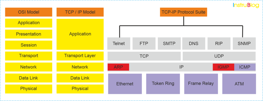
3. Ethernet (TCP/IP) Communication Protocols
- Ethernet is a widely used local area network (LAN) technology defined by the Institute of Electrical and Electronics Engineers (IEEE).
- TCP/IP (Transfer Control Protocol/Internet Protocol) is the set of protocols used for communication over the Internet and most private networks.
- In an Ethernet network, there are two types of network nodes: Data Terminal Equipment (DTE) and Data Communication Equipment (DCE).
- DTE devices are the endpoints that generate or are the destination of data, such as personal computers (PCs), workstations, and print servers.
- DCE devices are intermediate devices that receive and retransmit data frames within a network, including routers, switches, and repeaters.
- Ethernet networks use IP (Internet Protocol) for routing and addressing within the network.
- The baud rate, or data transfer rate, of Ethernet networks can vary but commonly reaches speeds of 100 Mbps (megabits per second).
- Ethernet networks can span distances of a few kilometers, making them suitable for local area networks within buildings or campuses.
- The number of nodes that can be connected in an Ethernet network is typically limited to 255 devices, allowing for efficient communication and network management.

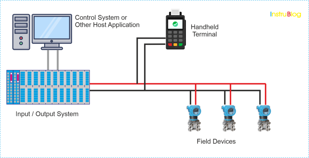
4. HART (Highway Addressable Remote Transducer) Protocols
- HART (Highway Addressable Remote Transducer) is a master-slave communication protocol.
- It is commonly used in various modes such as point-to-point or multidrop configurations for communication between smart field instruments and central control/monitoring systems.
- The protocol allows for the presence of two masters: a primary master, typically the control/monitoring system, and a secondary master, such as a handheld communicator, which can be used without interfering with the primary master’s communication.
- In a multidrop configuration, the maximum number of devices that can be connected to the network is typically limited to 15.
- HART supports various network topologies including point-to-point, multidrop, and wireless mesh.
- The protocol utilizes two simultaneous communication channels: a 4-20mA analog signal and a digital signal, allowing for both analog and digital data transmission.
- The bit values of 0 and 1 in the digital signal are represented by specific signal frequencies, with a frequency of 2200Hz for bit value 0 and 1200Hz for bit value 1.

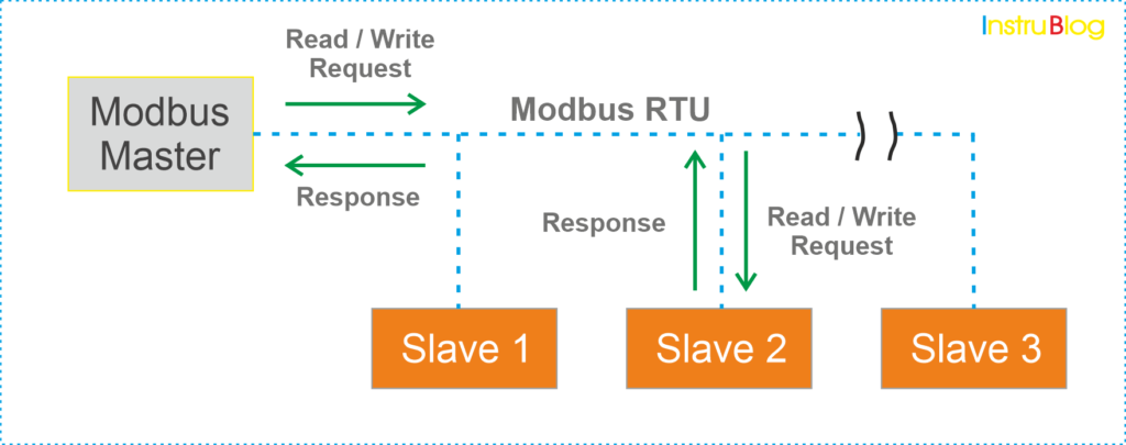
5. Modbus RTU Communication Protocols
- Modbus RTU is an open serial protocol derived from the Master-slave architecture, initially developed by Modicon (now Schneider Electric).
- RTU stands for Remote Terminal Unit, which refers to the devices communicating using this protocol.
- Modbus RTU has gained wide acceptance in various industries due to its ease of use and reliability.
- Modbus RTU messages are structured as simple 16-bit data packets, including a CRC (Cyclic Redundancy Check) for error detection and ensuring message integrity.
- The simplicity of Modbus RTU messages contributes to the protocol’s reliability and efficient communication.

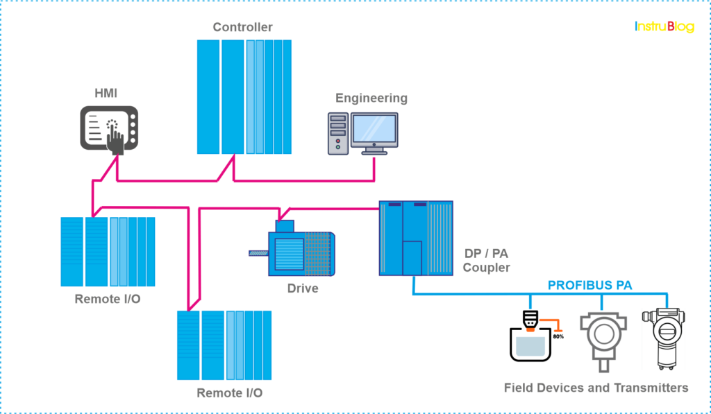
6. Profibus Communication Protocols
- Profibus is a communication protocol that utilizes three separate layers of the OSI model: Application Layer, Data Link Layer, and Physical Layer.
- The Application Layer of Profibus supports various types of messaging, including cyclic and acyclic data exchange, diagnosis, alarm handling, and isochronous messaging.
- Profibus does not define layers three to six of the OSI model.
- The Data Link Layer is completed by a Field Bus Data Link (FDL), which combines master-slave and token passing techniques.
- In the Physical Layer, Profibus systems can use three types of media: standard twisted pair wiring system (RS485), fiber optic transmission, and Manchester Bus Power (MBP), which is a safety-enhanced system for explosive environments.
- Profibus uses a Bus Topology, where devices are attached to a central bus line wired throughout the system.
- Profibus DP (Decentralized Periphery) devices are peripheral devices that send their output to the master and form passive stations on the network.
- All Profibus DP devices have the same priority, and network communication originates from the master.
- The maximum frame size in Profibus is 244 bytes.
- The maximum number of nodes on a Profibus network is 126, with a maximum of 32 nodes per slave.
- The baud rate for Profibus can range from 5 to 12 Mbps.
- The maximum length of a Profibus network is 15 km.

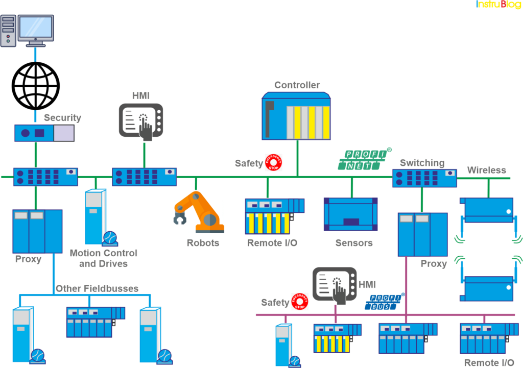
7. ProfiNet Communication Protocols
- Profinet is an Industrial Ethernet protocol.
- It offers faster communication with more bandwidth and supports larger message sizes compared to other protocols.
- Profinet is a newer protocol based on Ethernet, specifically designed for industrial communication.
- The physical interface used for Profinet is a standard RJ-45 Ethernet Jack, and the Profinet cables are typically identified by their green color.
- Profinet devices have three types of addresses: IP address, MAC address, and Device name. While IP and MAC addresses are used by all Ethernet devices, the Device Name is unique to Profinet devices.
- Profinet’s higher speed and increased flexibility have made it increasingly popular as a communication protocol in industrial applications.
- The use of Profinet allows for improved performance and integration in industrial automation systems.

8. Interbus Communication Protocols
- Interbus is a serial bus system designed for transmitting data between control systems such as PLCs, PCs, and robot controllers.
- It is a widely used field bus system in the automation industry and follows European standards.
- Interbus utilizes spatially distributed I/O modules that connect to various sensors and actuators, including temperature sensors and other devices.
- The network topology commonly used in Interbus is a ring topology, where all devices are actively integrated into a closed transmission path.
- This topology ensures reliable and efficient communication between the connected devices.
- Interbus provides a robust and standardized solution for data transmission in industrial automation applications.