
High input impedance, a single gain resistor and excellent common mode rejection make it the first choice for tiny sensor signals.
An instrumentation amplifier amplifies the tiny difference between two inputs while rejecting the voltage common to both. That makes it ideal for strain gauges, load cells, thermocouples and medical signals.
What Is an Instrumentation Amplifier?
An instrumentation amplifier is a precision differential amplifier with buffered inputs and gain set by one external resistor. It builds on the differential amplifier by adding high impedance input stages.
Sensors such as bridges produce millivolt signals riding on a much larger common voltage. The amplifier must boost the difference and ignore the rest.
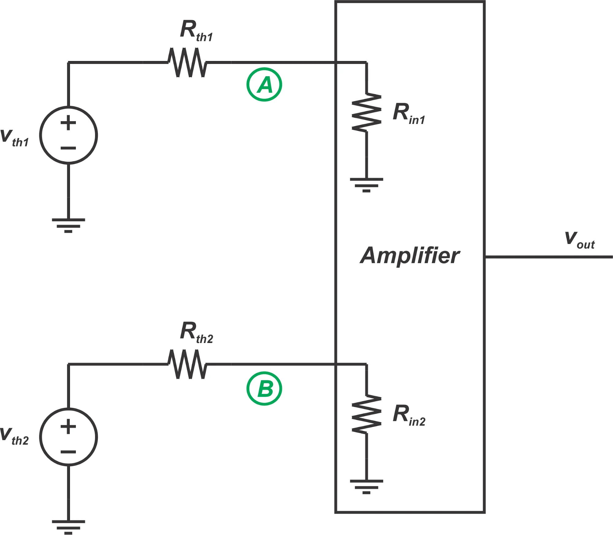
Both inputs connect straight to non inverting op amp inputs, so they draw almost no current. This means the source resistance of the sensor does not change the gain.
Our guide on op amp basics covers the building block used three times inside this circuit.
How the Three Op Amp Circuit Works
The first stage amplifies the differential signal by a factor set by RG, while common mode voltage passes through at a gain of one. This greatly improves the ratio of wanted to unwanted signal.
The output stage is a difference amplifier that removes the remaining common mode voltage. Its matched resistors decide how much common mode rejection you finally get.
Integrated parts like the AD620 and INA128 laser trim these resistors. That gives far better matching than discrete resistors on a PCB.
Instrumentation Amplifier Gain Formula
AD620 and AD8221: G = 1 + 49.4 kΩ ÷ RG
Worked example, AD620 for a gain of 100:
RG = 49.4 kΩ ÷ (G minus 1)
RG = 49.4 kΩ ÷ 99 = 499 Ω
Bridge output 10 mV × 100
Output = 1.0 V
Analog Devices notes the AD620 internal resistors are trimmed to 24.7 kΩ, so standard 1 percent resistors give popular gains. Use a low temperature coefficient resistor for RG, because its drift directly affects gain.
The amplified signal can then feed an ADC, as explained in ADC working principle. Choose the gain so the full sensor range uses most of the ADC range.
4 Secret Specs That Decide Accuracy
Analog Devices lists CMRR near 100 dB for the AD8221 and about 95 dB for the AD620 at a gain of 10. Higher gains usually give even better CMRR.
Offset and noise matter most for millivolt signals. Our signal to noise ratio calculator helps judge whether the signal will stand clear of noise.
Instrumentation Amplifier vs Differential Amplifier
| Feature | Differential Amplifier | Instrumentation Amplifier |
|---|---|---|
| Input impedance | Set by resistors, moderate | Very high |
| Gain setting | Several matched resistors | One resistor RG |
| CMRR | Limited by resistor matching | High, trimmed on chip |
| Source resistance effect | Changes gain | Negligible |
| Cost | Lower | Higher |
A simple difference amplifier loads the sensor and needs precise resistor pairs. The instrumentation amplifier avoids both problems.
For single ended signals, a plain voltage follower or non inverting stage may be enough. Use the in amp whenever the signal is differential or floating.
Types of In Amp Designs
Classic topology with two buffers and a difference stage.
Uses fewer parts but lower CMRR at high frequency.
AD620, AD8221 and INA128 with trimmed resistors.
Chopper stabilized or programmable gain versions.
Integrated parts are the usual choice because trimming beats any hand built design. Programmable gain versions let a microcontroller change range on the fly.
Zero drift parts suit slow signals such as weigh scales and thermocouples, where offset drift over temperature would otherwise dominate.
Where an Instrumentation Amplifier Is Used
Bridge sensors such as the strain gauge and load cell are the classic application. Their output is tiny and sits at half the excitation voltage.
Current sensing across shunt resistors is another common use. The high CMRR ignores the large common voltage on the shunt.
Gain Resistor Calculator
Use 50 kΩ as the constant for INA128 style parts. Always confirm the constant in the chosen device datasheet.
- Very high input impedance.
- Excellent common mode rejection.
- Gain set by one resistor.
- Low drift and low noise options.
- Higher cost than simple op amps.
- Output swing limited near the rails.
- Input common mode range must be checked.
- RG drift directly affects gain.
Analog Devices In Amp Design Guide
Three Op Amp Circuit Video
Instrumentation Amplifier FAQ
Related Articles
- Differential Amplifier and CMRR
- Op Amp Basics
- Signal Conditioning in Instrumentation
- Wheatstone Bridge Applications
- Ground Loop Causes and Prevention
External References
- In Amp Designer Guide, Analog Devices
- Three Op Amp In Amps, All About Circuits
- In Amp Circuit Design, Electronics Tutorials
- Instrumentation Amplifier, Wikipedia
What We Learn Today
- Buffered inputs and one gain resistor make precise differential amplification easy.
- CMRR, gain drift, offset and noise decide real accuracy.
- Integrated parts beat discrete builds because their resistors are trimmed.