
Flow Measurement · Ultrasonic · Process Instrumentation
Ultrasonic Flow Meter: Working Principle, Types, Selection and Installation
A complete guide to ultrasonic flow meters: how transit-time and Doppler principles work, inline vs clamp-on installation, single-path vs multipath, selection guide, installation requirements and troubleshooting.
An ultrasonic flow meter measures fluid flow by sending high-frequency sound waves through the pipe and analysing how the fluid affects those waves. It has no moving parts, creates no pressure drop, and can measure flow in both directions with equal accuracy. For large-diameter pipes, clamp-on models can be installed without breaking into the pipe at all. These qualities make the ultrasonic flow meter one of the most versatile and widely deployed measurement technologies in the process industry today.
You will find ultrasonic flow meters on water distribution networks, oil and gas pipelines, custody transfer stations, chemical plants, wastewater treatment facilities and district energy systems. They are the first choice wherever a non-intrusive measurement is needed, wherever the fluid is aggressive or ultra-pure and cannot contact a sensor, or wherever a large pipe diameter makes traditional insertion methods expensive.
This guide covers everything you need to know about ultrasonic flow meters: how both measurement principles work, the difference between inline and clamp-on designs, single-path vs multipath configurations, how to select the right type for your application, installation requirements and the most common problems found in service. For an overview of all flow meter technologies, see our article on types of flow meters and how to choose the right one.
What Is an Ultrasonic Flow Meter?
An ultrasonic flow meter is a device that measures the velocity of a fluid inside a pipe using high-frequency sound waves, typically in the range of 100 kHz to 1 MHz. It converts the measured velocity into a volumetric flow rate by multiplying by the known cross-sectional area of the pipe.
The key distinguishing feature of an ultrasonic flow meter is that it uses sound waves rather than mechanical components to make the measurement. This gives it several inherent advantages: no moving parts to wear, no obstruction to flow, no pressure drop across the meter, and the ability to measure without physical contact with the fluid in clamp-on designs.
Ultrasonic flow meters work on one of two physical principles: the transit-time (or time-of-flight) principle, which is used for clean liquids and gases, or the Doppler principle, which is used for liquids containing particles or bubbles. Understanding the difference between these two principles is the most important foundation for selecting and applying an ultrasonic flow meter correctly.
Transit-Time Principle: How It Works
The transit-time ultrasonic flow meter is the most widely used type in industry. It is the standard choice for clean liquids and gases. It works by measuring the tiny difference in travel time between a sound pulse sent in the direction of flow and one sent against the direction of flow.
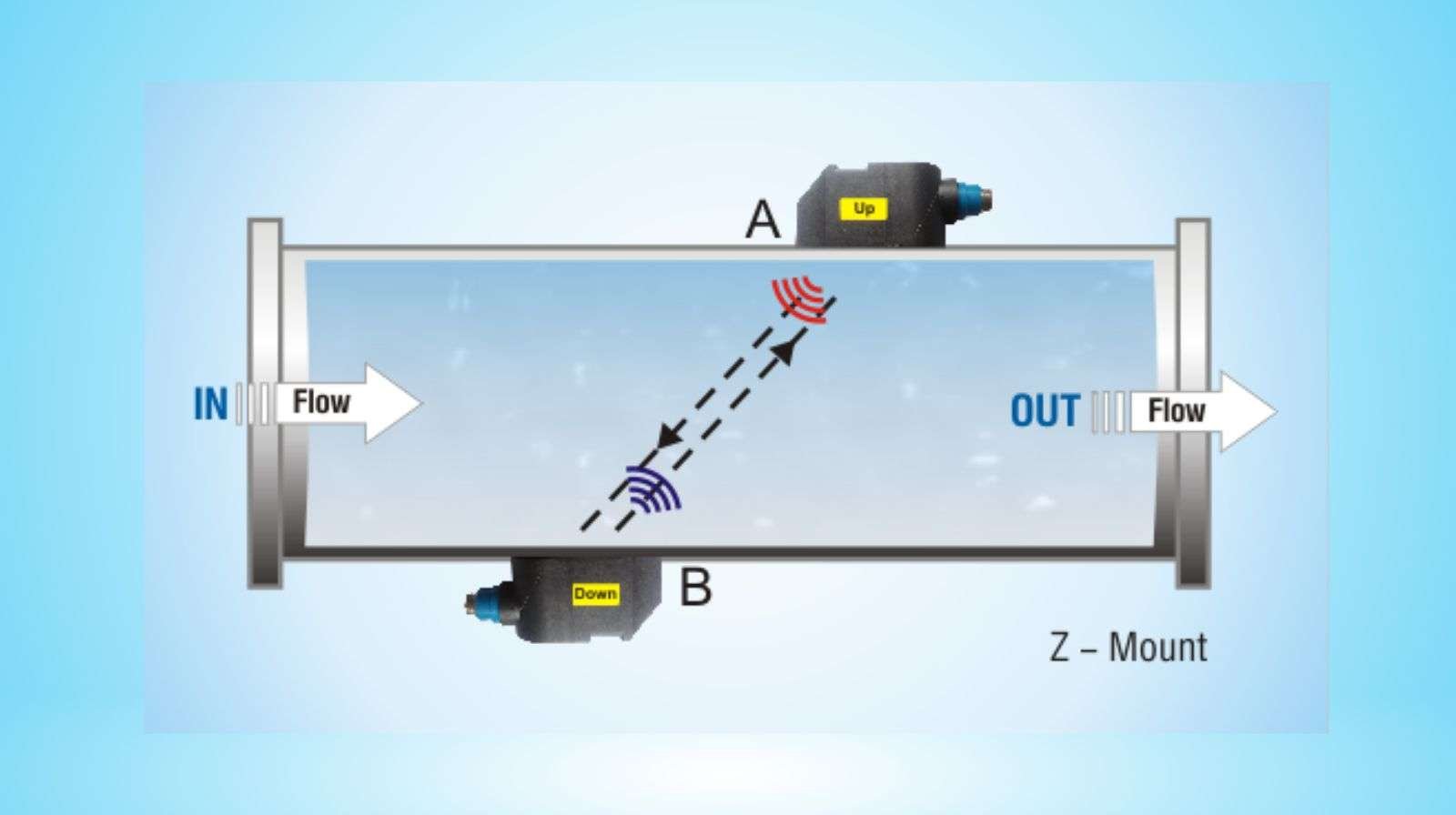
Here is the physics in simple terms: sound travels faster when it is moving with the flow than when it is moving against it. The faster the fluid flows, the bigger this time difference. By measuring the time difference precisely, the meter calculates the average fluid velocity along the acoustic path.
Figure 1: Transit-time principle. Transducer A sends a pulse to Transducer B (downstream, with the flow) in time t_AB. Transducer B sends a pulse back to A (upstream, against the flow) in time t_BA. Since t_BA is always slightly longer than t_AB when fluid is flowing, the time difference (t_BA minus t_AB) is directly proportional to fluid velocity.
The transit-time formula explained simply
When there is no flow, t_AB and t_BA are identical. The time difference is zero. The moment fluid starts flowing, the downstream pulse (A to B) arrives slightly earlier and the upstream pulse (B to A) arrives slightly later. The time difference grows linearly with flow velocity. The processor calculates velocity using:
V = (L / 2 cos θ) × (t_BA - t_AB) / (t_AB × t_BA)
Where: V = fluid velocity (m/s) | L = acoustic path length (m) | θ = angle of acoustic path to pipe axis | t_AB = transit time downstream (s) | t_BA = transit time upstream (s)
Doppler Principle: How It Works and When to Use It
The Doppler ultrasonic flow meter uses a completely different physical principle. Instead of measuring travel time differences between two transducers, it sends a continuous ultrasonic beam into the fluid and measures the frequency shift of the signal reflected back from particles or bubbles moving with the fluid.
This is the same Doppler effect you experience when an ambulance siren changes pitch as it passes you. The frequency of sound waves shifts when the source or the reflector is moving. In a Doppler flow meter, the reflectors are the particles or bubbles in the fluid. The faster they move (and therefore the faster the fluid flows), the greater the frequency shift in the returned signal.
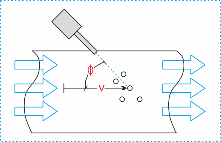
Figure 2: Doppler principle. A single combined transducer transmits an ultrasonic beam at frequency f0. Particles or bubbles in the fluid reflect the beam back at a shifted frequency. The frequency shift (Δf) is proportional to fluid velocity.
| Feature | Transit-Time | Doppler |
|---|---|---|
| Measurement principle | Time difference between upstream and downstream pulses | Frequency shift of reflected signal from particles/bubbles |
| Requires reflectors? | No. Needs clean, homogeneous fluid. | Yes. Fluid must contain particles or bubbles. |
| Best for | Clean water, chemicals, hydrocarbons, natural gas, district heating | Wastewater, slurries, sewage, aerated liquids, abrasive fluids |
| Not suitable for | Fluids with suspended solids, entrained gas, two-phase flow | Clean liquids with no suspended material |
| Typical accuracy | ±0.5% to ±1.0% of reading (inline) / ±1% to ±2% (clamp-on) | ±2% to ±5% of reading (less accurate than transit-time) |
| Used for custody transfer? | Yes, with certified multipath meters (API Chapter 5.8, AGA-9) | No. Not accurate enough for fiscal measurement. |
| Transducer arrangement | Two separate transducers (one upstream, one downstream) | Often one combined transmit/receive transducer |
Inline vs Clamp-On Ultrasonic Flow Meters
Beyond the measurement principle, ultrasonic flow meters are also divided by how they are physically installed in the pipe. There are two main installation methods: inline (wetted) and clamp-on (non-intrusive).
Inline (Wetted) Ultrasonic Flow Meter
- The meter has its own flow body (spool piece) that is installed in-line with the pipe via flanged or wafer connections
- Transducers are mounted directly in contact with the fluid or into the pipe wall of the spool piece
- Provides the highest accuracy because transducer positions are fixed and precisely controlled
- The pipe bore is known exactly, improving volumetric calculation accuracy
- Requires process shutdown and pipe cutting for installation
- Best choice for custody transfer, fiscal metering and high-accuracy process control
- Available in sizes from DN15 (0.5 inch) to DN3000 (120 inch) and larger
Clamp-On Ultrasonic Flow Meter
- Transducers are clamped to the outside of an existing pipe without cutting or drilling
- Ultrasonic signals pass through the pipe wall and into the fluid
- Completely non-intrusive: no contact with the process fluid
- Can be installed on any pipe material: steel, stainless steel, PVC, copper, cast iron
- Installation in minutes without process shutdown
- Portable versions can be moved between measurement points
- Lower accuracy than inline due to uncertainty in pipe wall thickness and bore dimensions
- Best for temporary measurement, check metering, large pipes, aggressive fluids
Figure 3: Inline meters use a dedicated spool piece with transducers inside the flow body. Highest accuracy but requires pipe cutting. Clamp-on meters clamp to the outside of any existing pipe. No pipe break needed but accuracy is slightly lower.
Single-Path vs Multipath Ultrasonic Flow Meters
Both inline and clamp-on ultrasonic meters can be configured with one acoustic measurement path (single-path) or multiple paths crossing the pipe at different heights (multipath). The number of paths directly affects measurement accuracy and immunity to flow profile disturbances.
| Configuration | How it works | Accuracy | Best for |
|---|---|---|---|
| Single-path (1 path) | One pair of transducers. One acoustic path crosses the pipe. The measured velocity on that one path is used to represent the average pipe velocity using a correction factor. | ±1% to ±2% typical | General process monitoring, check metering, clamp-on applications, smaller pipes |
| 2-path | Two acoustic paths cross the pipe at different angles or heights. The average of both paths is used. Significantly better immunity to flow profile asymmetry. | ±0.5% to ±1% | Process control, billing metering in water utilities, medium accuracy requirements |
| 4-path (standard for custody transfer) | Four paths at different vertical positions sample the velocity profile across the pipe cross-section. The weighted average gives a highly accurate representation of the true mean velocity. | ±0.2% to ±0.5% | Custody transfer of oil, gas and water. Fiscal metering where money changes hands based on the reading. |
| 5-path and above | Additional paths at the pipe centreline and at angled positions cover the full velocity profile more completely. Used in the most demanding accuracy applications. | Better than ±0.15% | Hydropower turbine efficiency testing, gas transmission custody transfer, reference meters |
For gas custody transfer, the AGA Report No. 9 standard governs multipath ultrasonic meter requirements. For liquid hydrocarbons, API Chapter 5.8 applies. Both standards typically require a minimum of 4 measurement paths for fiscal metering.
Clamp-On Transducer Mounting Methods: V, Z and W
For clamp-on ultrasonic flow meters, the transducers can be positioned on the pipe in three ways depending on the pipe size, pipe material and the meter's requirements. Each method results in a different acoustic path through the fluid.
| Method | How it works | Pipe diameter range | Notes |
|---|---|---|---|
| V Method (Reflective) | Both transducers are mounted on the same side of the pipe. The signal travels diagonally through the fluid, reflects off the opposite pipe wall and travels back. The acoustic path makes a V shape. | DN20 to DN300 (0.75 to 12 inch). Most common method. | Most widely used for small to medium pipes. The signal reflects off the opposite wall, so good pipe wall contact on both sides is needed. Not suitable for pipes with heavy deposits on the inside wall. |
| Z Method (Direct) | One transducer is mounted on each side of the pipe, directly opposite each other. The signal travels straight across the pipe diameter in a Z path. | DN100 to DN3000 (4 to 120 inch). For medium to large pipes. | Best for large diameter pipes or when the pipe wall is thick, dirty or lined. More direct signal path gives stronger signal. Requires access to both sides of the pipe for transducer mounting. |
| W Method (Double Reflection) | Both transducers on the same side. Signal reflects twice off opposite walls, making a W shape. Longer acoustic path through the fluid. | DN10 to DN100 (0.4 to 4 inch). For small pipes. | Used on small-diameter plastic pipes where the V method path would be too short for reliable measurement. Double reflection gives a longer effective path length. |
Installation Requirements: Straight Pipe Runs
One of the most common causes of ultrasonic flow meter errors in the field is insufficient straight pipe upstream or downstream of the meter. Ultrasonic meters measure velocity across a defined acoustic path. If the flow profile is disturbed (swirling, asymmetric or turbulent due to bends, valves or pumps nearby), the measured path velocity does not represent the true average velocity and the reading will be inaccurate.
| Upstream disturbance | Minimum upstream straight pipe required | Downstream required |
|---|---|---|
| Single elbow in one plane | 10D (minimum) | 5D |
| Two elbows in the same plane | 15D | 5D |
| Two elbows in different planes | 20D to 25D | 5D |
| Fully open gate or ball valve | 10D to 15D | 5D |
| Partially open control valve | 30D to 50D | 5D to 10D |
| Pump discharge | 25D to 30D | 5D |
| Reducer (pipe reduction upstream) | 15D | 5D |
| Custody transfer applications | 20D to 50D (per AGA-9 or API 5.8) | 10D |
- Pipe must be completely full. A partially empty pipe creates a gas-liquid interface that scatters the ultrasonic beam and makes measurement impossible. Install on horizontal pipe where possible, or on vertical pipe with upward flow to ensure the pipe stays full.
- Do not install at the highest point of the pipe. Gas pockets accumulate at high points and will enter the acoustic path, disrupting measurement.
- Do not install immediately downstream of a pump. Pumps create significant flow turbulence and can also introduce entrained air. Allow at least 25-30D of straight pipe between a pump and the meter location.
- Use acoustic couplant gel on clamp-on transducers. Without couplant, air gaps between the transducer face and the pipe wall will block the ultrasonic signal completely. Apply a continuous layer of ultrasonic coupling gel before clamping the transducers.
- Enter the correct pipe dimensions. For clamp-on meters, accurately measure and enter the pipe outer diameter, wall thickness and material. Errors in these parameters directly translate to errors in flow calculation.
Ultrasonic Flow Meter Selection Guide
| Application requirement | Recommended type | Why |
|---|---|---|
| Clean water, drinking water, district heating | Transit-time, inline or clamp-on | Clean fluid suits transit-time perfectly. Clamp-on is ideal for retrofitting existing water mains without shutdowns. |
| Wastewater or sewage with suspended solids | Doppler or transit-time with open-channel option | Solids and bubbles in sewage suit the Doppler principle. Transit-time may work on moderately dirty wastewater if solids content is low and consistent. |
| Oil and gas custody transfer | Transit-time, inline, 4-path or more | Highest accuracy requirement. Multipath inline meter with API 5.8 or AGA-9 certification. Clamp-on not acceptable for fiscal metering. |
| Natural gas pipeline measurement | Transit-time, inline multipath, AGA-9 compliant | Gas measurement is a primary application of transit-time ultrasonic meters. Multiple paths essential to achieve AGA-9 accuracy requirements. |
| Aggressive, corrosive or ultra-pure chemical | Transit-time, clamp-on | Clamp-on gives zero fluid contact. No wetted parts to corrode or contaminate. Ideal for HF acid, ultra-pure semiconductor process chemicals. |
| Large diameter pipe (above DN300) | Clamp-on transit-time, Z method | Inline meters become very expensive at large diameters. Clamp-on with Z method transducers is far more cost-effective and avoids process shutdown for installation. |
| Temporary or check measurement | Portable clamp-on transit-time | A single portable clamp-on meter can check multiple points in a plant in one day without any process interruption. Ideal for energy audits and meter verification. |
| Slurry, thick mud or abrasive liquid | Doppler clamp-on | High solids content suits Doppler. Clamp-on avoids transducer damage from abrasion. Accept lower accuracy (2-5%) for these difficult fluids. |
Advantages and Limitations of Ultrasonic Flow Meters
Advantages
- No moving parts. Nothing to wear, jam or fail mechanically. Very long service life with minimal maintenance.
- Zero pressure drop. The measurement creates no restriction to flow. No energy wasted overcoming a differential pressure.
- Bidirectional measurement. Measures flow equally accurately in both directions without any reconfiguration.
- Non-intrusive option. Clamp-on designs require no pipe penetration and zero fluid contact.
- Wide pipe size range. Suitable from DN15 to DN3000 and larger. No other technology covers this range as cost-effectively at the large end.
- No minimum conductivity requirement. Works on any liquid or gas, unlike electromagnetic flow meters which need conductive fluids.
- High accuracy available. Multipath inline meters achieve better than ±0.2% for custody transfer.
Limitations
- Transit-time requires clean fluid. Suspended solids or entrained gas above about 2% by volume disrupt the signal and cause errors or complete measurement loss.
- Doppler accuracy is lower. Doppler meters are typically only accurate to ±2-5%. Not suitable for billing or custody transfer.
- Requires straight pipe runs. More sensitive to flow profile disturbance than differential pressure or electromagnetic meters. Poor installation causes significant errors.
- Clamp-on needs accurate pipe data. Wall thickness, outer diameter and pipe material must be accurately measured and entered. Errors in pipe dimensions cause proportional flow errors.
- Sensitive to pipe deposits. Scale, corrosion or internal coating on the pipe wall attenuates the clamp-on signal and can prevent measurement entirely.
- Higher cost than DP or electromagnetic. Inline ultrasonic meters at small pipe sizes are more expensive than equivalent electromagnetic flow meters.
Common Ultrasonic Flow Meter Problems and How to Fix Them
| Problem | Likely cause | Fix |
|---|---|---|
| No signal / signal loss (clamp-on) | Insufficient acoustic couplant between transducer and pipe. Pipe heavily scaled internally. Pipe has a plastic liner creating an air gap. Transducer spacing incorrect. | Clean pipe surface and reapply couplant gel. Check signal strength indicator on transmitter (typically Q value or signal quality %). Verify correct transducer spacing per meter's calculated value. Consider Z method if V method signal is weak. On lined pipes, use plug-in insertion transducers. |
| Erratic or noisy reading | Gas bubbles or particles in normally clean fluid. Flow profile disturbance (installation too close to a bend or valve). Electrical interference on signal cables. Pipe partially empty. | Check upstream for pumps, valves or elbows too close to meter. Verify pipe is running full. Increase damping on transmitter output. Check cable shielding and grounding. Verify fluid is clean enough for transit-time measurement. |
| Reading consistently high or low vs reference | Incorrect pipe inner diameter entered in transmitter. Wrong wall thickness for clamp-on. Insufficient straight pipe upstream causing flow profile error. Wrong velocity profile factor (K factor). | Measure pipe dimensions carefully and re-enter. Use pipe manufacturer's data for wall thickness rather than nominal values. Check upstream straight pipe run and relocate if insufficient. Verify K factor setting matches the actual pipe Reynolds number range. |
| Reads zero when flow is present | Flow direction opposite to meter configuration. Fixed zero offset set too high. Pipe empty at meter location (air pocket at high point). | Swap transducer connections or reverse flow direction in transmitter configuration. Check for air pockets at meter location and relocate to ensure full pipe. Check zero offset setting. |
| Works well at high flow but loses signal at low flow | Fluid velocity below the meter's minimum detectable velocity. Zero cutoff set too high. Pipe partially empty at low flow. | Check meter's minimum velocity specification (typically 0.03 to 0.1 m/s for transit-time). Reduce the low flow cutoff setting. For very low flows, consider a smaller pipe spool with the same flow rate to increase velocity at the meter location. |
Further Reading and External Resources
- AGA Report No. 9: Measurement of Gas by Multipath Ultrasonic Meters. The industry standard for natural gas custody transfer using ultrasonic flow meters. Published by the American Gas Association.
- Control Engineering: Upstream and Downstream Pipe Diameter Requirements. Practical guide to straight pipe run requirements for all flow meter technologies including ultrasonic.
- Omega Engineering: Doppler vs Transit-Time Ultrasonic Flow Meters. Clear comparison of both measurement principles with application guidance.
- Badger Meter: Ultrasonic Flow Meter Technology Overview. Technical overview of both transit-time and Doppler principles from a leading flow meter manufacturer.
Frequently Asked Questions: Ultrasonic Flow Meter
- Types of Flow Meters: A Complete Guide with Selection Chart
- How Electromagnetic Flow Meter Works
- Vortex Flow Meter Working Principle Explained
- Coriolis Flow Meter: Working Principle and Applications
- Signals in Instrumentation: AI, AO, DI and DO Explained
- Instrument Loop Checking: Step-by-Step Procedure
- Turndown Ratio in Flow Meters Explained
What we learn today
- Ultrasonic flow meters use two principles: transit-time (measures time difference between downstream and upstream pulses, for clean fluids) and Doppler (measures frequency shift from reflected particles, for dirty or aerated fluids). Never use transit-time on a dirty fluid or Doppler on a clean one.
- Inline meters give the best accuracy by using a dedicated spool piece. Clamp-on meters are non-intrusive and install without cutting the pipe, making them ideal for retrofits, large pipes, aggressive fluids and temporary measurement.
- Multipath meters (4 paths or more) are required for custody transfer applications governed by AGA-9 (gas) or API Chapter 5.8 (liquid hydrocarbons). Single-path meters suit general process monitoring.
- Always install with a minimum of 10D straight pipe upstream and 5D downstream. Insufficient straight pipe is the most common cause of measurement error in the field. For partially open valves or pump discharges, increase to 20-30D upstream.


3 Comments