
Measure tens of amperes on a mains conductor while your microcontroller stays safely isolated, all through a magnetic field.
Current flowing in a conductor creates a magnetic field, and a Hall element converts that field into a voltage. This lets electronics measure AC and DC current without any electrical connection to the circuit.
What Is a Hall Effect Current Sensor?
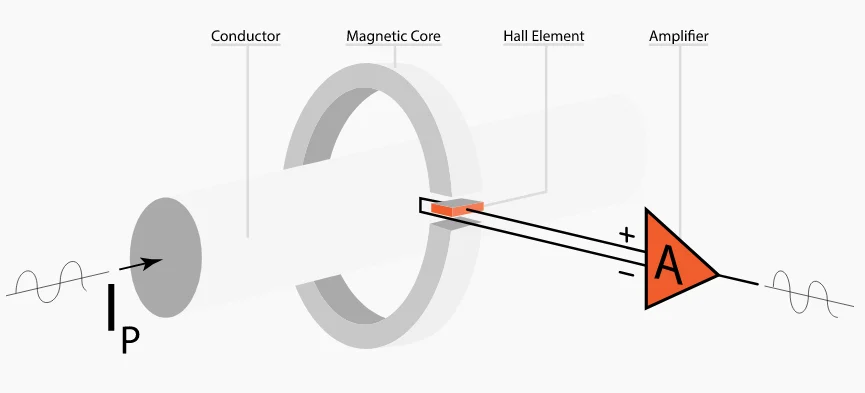
A Hall effect current sensor is a device that measures the magnetic field produced by a current carrying conductor with a Hall element and converts it into a proportional voltage or current output. It measures both AC and DC while keeping the measurement electronics galvanically isolated from the conductor.
The underlying physics is covered in how a Hall effect sensor works. Moving charges in a thin semiconductor are pushed sideways by the magnetic field, creating the Hall voltage.
All About Circuits notes that Hall sensing gives isolation without the power loss of a shunt resistor. That makes it attractive for high current and high voltage circuits.
Unlike a current transformer, it measures DC as well as AC. That is essential for batteries, solar and DC motor drives.
Hall Voltage Formula
Measured current = (V out minus V offset) ÷ Sensitivity
n = carrier density, q = electron charge, t = element thickness
ACS712 20 A example at 5 V supply:
Zero current output = 2.5 V
Sensitivity = 100 mV per A
V out = 3.1 V
Current = (3.1 minus 2.5) ÷ 0.1 = 6.0 A
The Allegro datasheet lists 100 mV per A sensitivity for the 20 A version and at least 2.4 kV RMS isolation. The 5 A and 30 A versions use 185 mV per A and 66 mV per A.
Negative current drives the output below 2.5 V, so AC appears as a swing around the midpoint. Firmware subtracts the offset before scaling.
4 Smart Sensor Designs
Core concentrates flux onto a Hall element, output amplified directly.
Secondary coil cancels the core flux, coil current is the output.
Conductor runs through the IC package, like ACS712.
Two Hall plates reject stray fields.
All About Circuits explains that closed loop designs use negative feedback, so drift in Hall sensitivity has little effect. They also respond faster and are more linear.
A smaller core air gap gives more magnetic gain but saturates earlier, lowering the maximum measurable current. Designers trade range against resolution.
Open Loop vs Closed Loop
| Feature | Open Loop | Closed Loop |
|---|---|---|
| Accuracy | About 1 to 2 percent | Better than 0.5 percent |
| Temperature drift | Higher | Low |
| Bandwidth | Tens of kHz | Up to hundreds of kHz |
| Power use | Low | Higher, drives the coil |
| Cost and size | Lower | Higher |
Choose using the priorities in sensor selection criteria. Motor drives often use closed loop units in each phase.
Hall offset drifts with temperature, so auto zeroing at a known zero current improves accuracy in open loop systems.
Reading the Output With a Microcontroller
A 10 bit ADC on a 5 V reference gives 4.88 mV per count, which is about 49 mA per count with a 100 mV per A sensor. Use oversampling or a better ADC for finer resolution.
For AC loads, sample fast over whole cycles and compute RMS rather than a simple average. Twisting sensor wires, keeping them away from motor cables and adding a small RC filter all reduce noise.
Where Hall Sensing Is Used
In brushless DC motors, Hall current sensing works alongside Hall position sensors. Both rely on the same effect, although one senses current and the other senses rotor magnet position.
Output to Current Calculator
Measure the real offset at zero current rather than assuming exactly half supply. Supply variation shifts both offset and sensitivity on ratiometric sensors.
- Measures AC and DC.
- Galvanic isolation.
- Very low insertion loss.
- Compact module options.
- Offset drift with temperature.
- Sensitive to stray magnetic fields.
- Limited bandwidth in open loop units.
- Core saturation at overload.
Allegro ACS712 Datasheet PDF
ACS712 Module Video
Hall Effect Current Sensor FAQ
Related Articles
- How a Hall Effect Sensor Works
- Shunt Resistors in Instrumentation
- Current Transformer Working Principle
- ADC Working Principle
- Magnetic Proximity Sensors
External References
- ACS712 Datasheet, Allegro MicroSystems
- Open Loop and Closed Loop Hall Sensing, All About Circuits
- Hall Effect Sensor, Wikipedia
What We Learn Today
- Hall elements turn a conductor magnetic field into an isolated signal.
- Closed loop designs beat open loop on accuracy and drift.
- Subtract offset and divide by sensitivity to read current.