
A gauge pressure transmitter is the most widely used pressure instrument in process plants. It measures pressure referenced to the local atmosphere, outputting 4 mA at zero gauge pressure and 20 mA at the calibrated upper range value.
This guide covers the working principle, how the 4 to 20 mA span is set, six main applications, and an interactive mA to-pressure calculator with a live signal slider.
Gauge pressure is measured relative to the local atmosphere. Zero gauge means the process is at atmospheric pressure.
The transmitter output of 4 mA always corresponds to zero gauge, regardless of what the absolute pressure actually is.
How a Gauge Pressure Transmitter Works
The sensing element is a thin diaphragm exposed to process pressure on one side and to atmosphere on the other through a small vent hole in the housing.
The diaphragm deflects in proportion to the difference between process pressure and local atmospheric pressure. This difference is the gauge pressure.
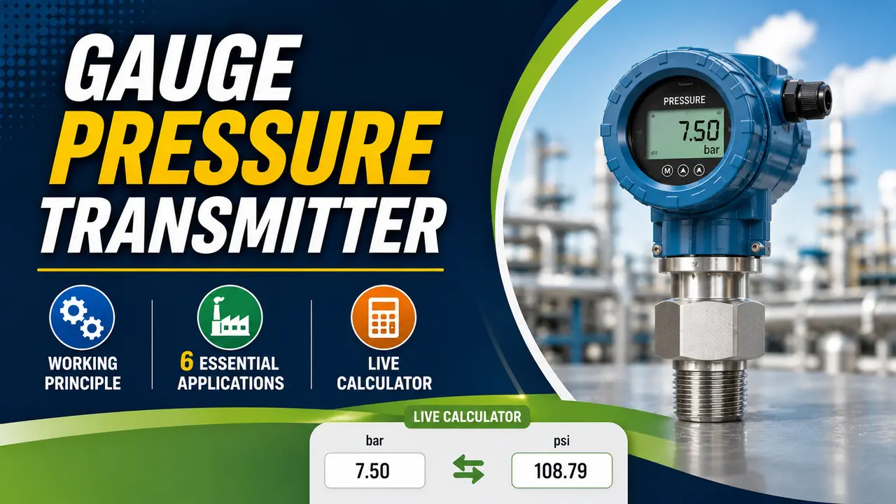
The deflection is measured by a capacitance, piezoresistive silicon, or strain gauge sensor element. The signal is amplified and linearised, producing a 4 to 20 mA output proportional to gauge pressure.
For a full overview of sensor types, see the pressure transducer and sensor guide.
The atmospheric vent means the reading shifts when barometric pressure changes with weather or altitude.
On high range transmitters (hundreds of bar) this shift is negligible. On low range transmitters (0 to 10 kPa gauge), a 1 kPa barometric shift is 10% of span, which is significant enough to require an absolute transmitter.
LRV, URV, Span and Turndown: Setting the Transmitter Range
Every gauge pressure transmitter is characterised by four range parameters. Understanding them is essential for calibration and for specifying the correct transmitter for an application.
Live 4 to 20 mA Signal Visualiser
6 Essential Applications of Gauge Pressure Transmitters
Pipeline and Vessel Pressure Monitoring
The most common application. A gauge transmitter on a pipe or vessel feeds the DCS with a 4 to 20 mA signal.
High pressure alarms and shutdowns are triggered when the output reaches a preset milliamp threshold in the DCS.
Typical range: 0 to 500 kPa up to 0 to 400 barHydrostatic Level Measurement
A gauge transmitter at the bottom of an open tank converts liquid head directly to a level reading. For water, every 1 metre adds 9.81 kPa gauge.
The transmitter span is set to ρ × g × H_range, giving a 4 to 20 mA output linear with level.
Typical range: 0 to 50 kPa to 0 to 500 kPa depending on tank depthSteam and Boiler Pressure
Gauge transmitters on boiler drums and steam headers monitor steam pressure above atmosphere. All steam trips and alarms are stated in gauge pressure.
The span drift guide covers why steam service transmitters need more frequent verification.
Typical range: 0 to 2000 kPa (0 to 20 bar gauge)Compressed Gas and Air Supply
Instrument air headers, nitrogen blanket systems, and compressed gas distribution lines all use gauge pressure transmitters to monitor supply pressure. A drop in instrument air pressure below 500 kPa gauge triggers a plant wide alarm because it affects all pneumatic control valve actuators simultaneously.
Typical range: 0 to 1000 kPa (0 to 10 bar gauge)Filter and Strainer Monitoring
Two gauge transmitters, upstream and downstream of a filter, provide a simple pressure drop indication. As the filter loads, the difference between the two readings increases.
An alternative is a single DP transmitter across the filter. See the DP transmitter basics guide.
Typical range: 0 to 200 kPaHydraulic and Pump Discharge Pressure
Gauge transmitters on pump discharge lines confirm that the pump is developing pressure and that the downstream system is pressurised correctly. A gauge transmitter on pump suction monitors NPSH conditions. High discharge pressure alarms protect the pump casing and downstream piping from overpressure events.
Typical range: 0 to 10000 kPa (0 to 100 bar) for high pressure hydraulics4 to 20 mA Pressure Calculator
Gauge vs Absolute vs Differential: Which to Use
| Parameter | Gauge Transmitter | Absolute Transmitter | Differential Transmitter |
|---|---|---|---|
| Zero reference | Local atmosphere -- varies with altitude and weather | Perfect vacuum -- stable always | LP port of the transmitter |
| Reading at atmospheric pressure | 0 kPa (zero) -- easy for operators | 101.325 kPa -- must remember the offset | 0 kPa if LP and HP connected to same point |
| Best for | Pipework pressure, tank level, pump monitoring, steam systems -- any application above atmospheric where the offset from vacuum is irrelevant | Vacuum vessels, distillation columns, steam tables, altitude sensitive measurements | Flow across a restriction, level in a closed vessel, filter loading, density monitoring |
| Altitude effect | Reading shifts by local barometric variation (up to 2 kPa weather, several kPa at altitude) | No altitude or weather effect -- reference is sealed vacuum | No altitude effect -- both ports exposed to the same atmospheric environment |
| Typical output | 4 to 20 mA: 4 mA = 0 kPag, 20 mA = URV | 4 to 20 mA: 4 mA = LRV (can be near zero absolute), 20 mA = URV | 4 to 20 mA: 4 mA = zero DP, 20 mA = full scale DP |
Common Calibration Errors and How to Detect Them
The two most common errors on gauge pressure transmitters after installation are zero shift and span drift.
Zero Shift Detection
- Vent the transmitter to atmosphere with the isolation valve closed and equalise valve open
- The output must read exactly 4.000 mA. Any deviation is a zero error
- A zero error shifts the reading by a fixed offset across the entire range -- a 0.5% zero error produces 0.5% error at all pressures
- Caused by overrange, temperature change, mechanical shock, or long term drift of the sensor zero
- Fixed by re zeroing the transmitter at atmospheric pressure using the HART or local zero button
Span Drift Detection
- Apply a known reference pressure equal to 50% or 100% of the calibrated span using a deadweight tester or pressure calibrator
- The output must match the calculated mA for that pressure. Deviation is span error
- Span error is proportional -- a 1% span error produces 0% error at zero and 1% error at full scale, so it is not visible during a zero check alone
- Caused by diaphragm fatigue, chemical attack, or long term creep in the sensor element
- Always perform a two point check (zero and span) during scheduled calibration -- a zero check alone is insufficient
Watch: Pressure Transmitter Working Principle and 4-20 mA Signal
Gauge Pressure Transmitter Questions
External References
- Rosemount 3051 Gauge Pressure Transmitter Data Sheet -- Emerson
- 2600T Pressure Transmitter Series -- ABB
What We Learn Today
- Gauge pressure uses local atmosphere as zero -- 4 mA output always means zero gauge pressure
- P = LRV + [(mA − 4) / 16] × Span -- the core conversion formula
- Span = URV minus LRV; turndown = URL divided by span
- Gauge transmitters shift with altitude and weather -- use absolute for low range or vacuum applications
- Zero shift and span drift are the two most common post installation errors -- always do a two point calibration check
- Steam and hydraulic pressure are always specified in gauge -- relief valve setpoints are gauge by definition