
A single controller failure in a running plant is not a small event. It's the difference between a smooth, uneventful shift and an emergency shutdown that costs real money and real risk.
That's the entire reason DCS redundancy exists as a design discipline rather than an optional extra. Plants running continuous processes, refineries, power stations, chemical units, simply cannot tolerate a single point of failure sitting between the control logic and the process it's managing.
This guide walks through the five layers of redundancy a well-designed DCS actually relies on, how bumpless switchover keeps the process blind to a failure, and the math behind why redundant pairs are so dramatically more reliable than a lone controller.
DCS controller redundancy is the practice of pairing critical hardware, controllers, I/O modules, communication networks, and power supplies, so that a single component failure never interrupts control of the process, and it works because a standby unit continuously mirrors the active unit's internal state and takes over instantly, without the process ever noticing the switch.
DCS Controller Redundancy: How this is Useful in Plants
DCS controller redundancy solves a problem that sounds simple on paper but gets expensive fast in reality: what happens the moment a controller stops working while it's actively running a live process?
In an office server room, a crashed application usually means an annoyed user and a restart.
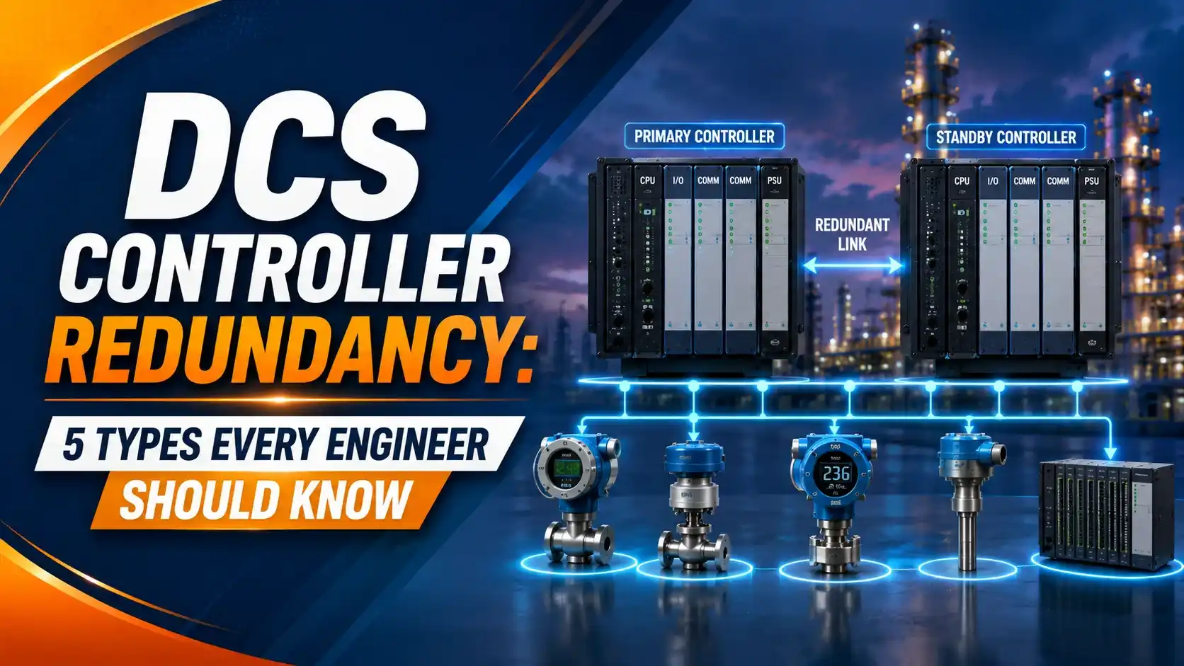
In a refinery distillation column or a power plant boiler, a controller that stops driving its outputs mid-cycle can mean a runaway temperature, an uncontrolled pressure buildup, or an unplanned trip that costs a full day of lost production to restart safely.
As explained in our broader distributed control system overview, distributed control systems were built from the ground up around the assumption that hardware eventually fails, not as an edge case, but as a certainty over a long enough operating life.
Redundancy is the architectural answer to that certainty. Instead of trying to build a controller that never fails, which is practically impossible, engineers pair critical components instead.
That way, when one component does fail, its partner is already tracking the exact same state and ready to take over before the process ever notices.
This differs meaningfully from the redundancy concepts covered in our PLC hot standby redundancy guide, since DCS platforms typically extend redundancy across a much wider architecture.
Controllers, I/O, networks, and power all get treated as a standard design philosophy in a DCS, rather than an add-on feature reserved for the most critical loops.
Inside a Redundant Controller Pair
Picture two identical controllers mounted side by side, connected by a dedicated high-speed synchronization link that has nothing to do with the regular control network.
Every scan, the active controller pushes its updated internal database, timers, counters, calculated values, and logic states, across that sync link to the standby.
When a failure is detected, the standby doesn't start cold. It picks up exactly where the primary left off, which is the entire secret behind what the industry calls a bumpless switchover.
5 Types of Redundancy in a Modern DCS
Controller Redundancy
A matched primary and secondary controller pair, synchronized continuously, so a hardware fault on the active unit triggers an automatic, bumpless switchover to the standby.
I/O Module Redundancy
Critical input and output channels are duplicated onto separate physical modules, so a single card failure doesn't blind the controller to a measurement or lose control of an output.
Network and Communication Redundancy
Dual, physically separate control network paths, often in a ring or dual-star topology, keep the controller talking to I/O and workstations even if one cable or switch fails, much like the ES/OS/AS network layers described in our DCS components guide.
Power Supply Redundancy
Independent power feeds and power supply modules mean a single supply failure, or even a full feed loss, doesn't take the controller or I/O rack down with it, a topic covered in more depth in our redundant power supply guide.
Field Device Redundancy
On the most critical measurement loops, dual transmitters or sensors feed independent signals, so a single field instrument failure doesn't blind the control strategy entirely.
Comparing the Five Layers at a Glance
| Redundancy Type | Protects Against | Typical Switchover Time |
|---|---|---|
| Controller redundancy | CPU hardware fault, firmware crash, memory failure | Under 50 milliseconds, often under 20 ms |
| I/O module redundancy | Single I/O card hardware failure | Effectively bumpless, no scan interruption |
| Network redundancy | Cable break, switch failure, network card fault | Sub-second, path reroutes automatically |
| Power supply redundancy | Power module failure or feed interruption | Instant, load transfers with no interruption |
| Field device redundancy | Single transmitter or sensor failure | Depends on voting logic, typically instant |
How Bumpless Switchover Actually Works
The word "bumpless" gets used a lot in redundancy discussions, and it deserves a proper explanation rather than a passing mention.
A switchover is bumpless when the transition from primary to secondary produces no step change, no glitch, and no lost scan in the controller's outputs. The process being controlled genuinely cannot tell that anything happened.
This is only possible because the standby controller was never sitting idle. It was continuously receiving synchronized copies of every relevant memory register, timer value, and internal calculation from the active controller, scan after scan.
When the switchover trigger fires, the standby simply continues executing from that exact state, as if it had been the one running the process all along.
Contrast that with a cold restart, where a backup controller boots up from a static configuration with no memory of what the process was doing a moment ago.
That's not redundancy in any meaningful sense, it's just a slower, more disruptive recovery, closer to the switchover-failure scenarios discussed in our redundancy switchover failure article.
Try It: Controller Availability Improvement Calculator
Enter a single controller's MTBF and MTTR, and this calculator shows exactly how much a redundant pair improves system availability, expressed in real downtime minutes per year.
Let Us Take an Example
Take a controller with a manufacturer-rated MTBF of 50,000 hours, roughly five and a half years of continuous operation between failures, and a typical repair time of 4 hours to swap and reconfigure a failed unit.
MTBF = 50,000 hours
MTTR = 4 hours
Step 1: Single controller availability
A = MTBF ÷ (MTBF + MTTR)
A = 50,000 ÷ (50,000 + 4)
A ≈ 0.99992
Step 2: Single controller downtime per year
(1 − A) × 525,600 minutes
≈ 42.04 minutes per year
Step 3: Redundant pair unavailability
(1 − A)² ≈ (0.00008)²
≈ 6.4 × 10⁻⁹
Step 4: Redundant pair downtime per year
6.4 × 10−9 × 525,600 minutes
≈ 0.00336 minutes per year
Look at that gap for a second. A single controller with a genuinely strong reliability rating still adds up to about 42 minutes of expected downtime across a year.
Pair it with an identical standby, and that number drops to roughly 0.003 minutes, a fraction of a second, across the same year.
This is why redundancy earns its cost on critical control loops. The math isn't a marginal improvement, it's several orders of magnitude, and it's the reason plant reliability engineers treat controller redundancy as close to non-negotiable on anything that can't tolerate an unplanned trip.
How the System Actually Detects a Failure
None of this works without a fast, reliable way to know the primary has actually failed, rather than just being briefly slow.
Redundant controllers exchange a continuous heartbeat signal over the dedicated sync link, separate from the regular process control network. Miss enough consecutive heartbeats, or fail a set of internal diagnostic self-checks, and the system declares a fault and initiates switchover automatically.
According to this explanation of redundant signal configuration and bumpless switching in DCS systems, getting this diagnostic timing right is just as important as the hardware itself.
A switchover trigger that's too aggressive causes nuisance switches, while one that's too slow defeats the purpose of redundancy in the first place.
A Step-by-Step Approach to Specifying DCS Redundancy
Classify loops by criticality
Identify which control loops genuinely cannot tolerate an interruption before deciding where full redundancy is justified.
Start with controller redundancy on critical units
Prioritize controller-level redundancy first, since it protects the broadest range of failure modes for the investment.
Extend to I/O and network layers
Add I/O module and network redundancy on the specific channels and paths that would otherwise undermine the controller redundancy already in place.
Don't forget power
Confirm independent, properly rated power feeds exist for both halves of every redundant pair, since shared power defeats the purpose.
Reserve field device redundancy for the highest-value loops
Dual transmitters add real cost, so apply them where a single sensor failure would have serious consequences.
Test switchover under realistic conditions
Verify bumpless behavior during commissioning, not just on paper, using an actual forced switchover test.
Good Practices for DCS Redundancy Design
✓ Do
- Prioritize redundancy investment based on genuine process criticality, not a blanket policy
- Verify independent power feeds for both halves of every redundant pair
- Test actual switchover behavior during commissioning, not just review the design on paper
- Keep primary and secondary controllers on matched firmware versions at all times
✗ Don't
- Assume controller redundancy alone covers I/O, network, or power failure modes
- Share a single power feed across both halves of a redundant pair
- Leave switchover diagnostics at overly conservative default timing without reviewing them
- Skip periodic switchover testing once a system is commissioned and running
Worth Reading if You Want to Go Deeper
Questions Students and Technicians Often Ask
External References
- DeltaV Controller Redundancy, Emerson
- Configuration of Redundant Signals and Bumpless Switching in DCS Systems, Just Measure It
What we learn today
- DCS controller redundancy pairs a primary and secondary controller so a hardware failure triggers an instant, bumpless switchover instead of a process interruption.
- There are five common layers of DCS redundancy: controller, I/O module, network, power supply, and field device redundancy.
- Bumpless switchover works because the standby controller continuously mirrors the active controller's internal state over a dedicated sync link.
- A worked example showed a single controller with roughly 42 minutes of expected downtime per year, dropping to about 0.003 minutes per year once paired redundantly.
- A continuous heartbeat and diagnostic self-check system is what actually triggers the automatic switchover when a real failure occurs.