
An op amp, two resistors and two capacitors give a sharp second order filter without bulky inductors.
An active filter uses an op amp together with resistors and capacitors to shape the frequency response of a signal. The Sallen and Key circuit is the most popular way to build a second order low pass or high pass stage.
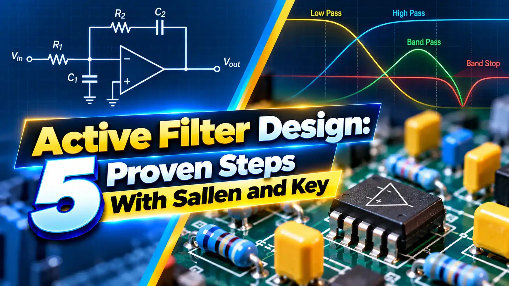
What Is an Active Filter?
An active filter is a filter circuit that combines an amplifying element, usually an op amp, with resistors and capacitors. Compared with the passive RC low pass and high pass filters, it can provide gain, buffering and sharper roll off without inductors.
A single RC stage rolls off at 20 dB per decade. A second order stage rolls off at 40 dB per decade, which removes noise and aliasing far more effectively.

The op amp output has low impedance, so the next stage does not load the filter. That is why an active filter is common just before an ADC in signal conditioning circuits.
The Sallen and Key topology, published in 1955, uses the op amp as a unity gain buffer with positive feedback through one capacitor. It is simple, stable and easy to tune.
Sallen and Key Formulas
Unity gain, R1 = R2: Q = √(C1 ÷ C2) ÷ 2
Worked Butterworth example, Q = 0.707:
C1 = 20 nF, C2 = 10 nF, R1 = R2 = 1.1 kΩ
Q = √(20 ÷ 10) ÷ 2 = 0.707
fc = 1 ÷ (2π × 1100 × √(20 nF × 10 nF))
fc ≈ 10.2 kHz
Circuit Cellar shows that equal component values give a Q of only 0.5, which rolls off gently. A 2 to 1 capacitor ratio gives the Butterworth Q of 0.707 with the flattest passband.
C1 is the capacitor from the midpoint to the output, and C2 goes from the op amp input to ground. Swapping resistors and capacitors turns the circuit into a high pass filter.
5 Proven Active Filter Design Steps
Step 5 is often skipped, and the filter then peaks or drifts. Circuit Cellar notes about 4 percent overshoot for the Butterworth step response, which a slow op amp can make worse.
Use stable capacitors such as C0G or film, explained in capacitor types. Ceramic types with high voltage coefficients shift the cutoff.
How the Filter Shapes the Signal
Before an ADC, the active filter removes frequencies above half the sampling rate, preventing aliasing. Our ADC working principle guide explains why this matters.
Cascading two second order stages gives a fourth order filter with 80 dB per decade roll off. Each stage then uses a different Q to achieve the overall Butterworth shape.
Filtering also improves the signal to noise ratio by cutting noise outside the useful band.
Filter Types and Topologies
Passes low frequencies, blocks noise above fc.
Blocks DC and low frequency drift.
Passes a band around a centre frequency.
Alternative inverting topology with good high frequency behaviour.
Sallen and Key is ideal for low Q low pass and high pass stages. Multiple feedback designs suit band pass filters and higher Q values.
Notch filters remove one frequency, such as 50 Hz mains hum, using twin T or state variable designs.
Response Types Compared
| Response | Passband | Roll Off | Step Response |
|---|---|---|---|
| Butterworth | Maximally flat | Moderate | Small overshoot |
| Bessel | Gentle droop | Slow | Almost no overshoot |
| Chebyshev | Ripple | Sharp | Large overshoot |
Butterworth is the default choice for most instrumentation. Bessel suits pulse and timing signals, where preserving the waveform shape matters.
For very small sensor signals, filter after amplification so the op amp noise does not dominate. Buffer high impedance sources first with a voltage follower.
Active Filter Calculator
Try equal capacitors to see Q fall to 0.5. Increase the C1 to C2 ratio to raise Q, but values above about 1 start to peak.
- No inductors needed.
- Low output impedance.
- Easy to cascade.
- Can add gain.
- Needs a power supply.
- Limited by op amp bandwidth.
- Component tolerance shifts fc and Q.
- Signal swing limited by rails.
TI Sallen and Key Analysis PDF
Second Order Filter Tutorial Video
Active Filter FAQ
Related Articles
- RC Low Pass and High Pass Filter
- Op Amp Basics
- Signal Conditioning in Instrumentation
- Analog to Digital Conversion
- Capacitor Types Explained
External References
- Analysis of the Sallen Key Architecture, Texas Instruments
- Sallen and Key Filter, Circuit Cellar
- Sallen and Key Filter Design, Electronics Tutorials
- Electronic Filter, Wikipedia
What We Learn Today
- Op amps let RC networks form sharp filters without inductors.
- Cutoff depends on RC values, and the capacitor ratio sets Q.
- Pick a fast op amp and stable capacitors for accurate results.