A device can talk perfectly on the bus and still show garbage on the SCADA screen because one line of its register table was read the wrong way. This article shows how to read any vendor table, convert 40001 style numbers to offsets and decode floats correctly.
Every Modbus slave publishes a table that tells the master where each value lives and how to decode it. Learn the four tables, the off by one trap, 32 bit floats and integer scaling with solved examples and a calculator.

What Is a Modbus Register Map?
A modbus register map is the table in a device manual that lists every value the device shares, with its address, data type, scaling, units and read or write access. The master uses this table to build each request, so a wrong address, data type or word order gives wrong readings even when communication is healthy.
- Four tables: coils (0x), discrete inputs (1x), input registers (3x) and holding registers (4x)
- 40001 is a documentation number; the request carries offset 0 with function code 03
- Each register is 16 bits, so a 32 bit float or long integer uses two registers
- Word order (ABCD, CDAB, BADC, DCBA) must match the device
- Integer values often need a scale factor such as divide by 10 or 100
The protocol itself only moves bits and 16 bit words, as covered in our page on how the Modbus protocol works. The meaning of each word comes from the vendor table, and the master chooses which table to read through the Modbus function codes it sends.
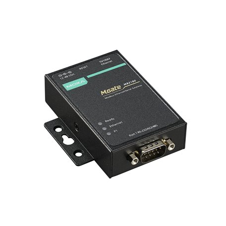
A gateway like the one above passes requests between Modbus TCP and RTU, but it never fixes a wrong address in the master. The same modbus register map rules apply whether the slave sits on Ethernet or on a serial line, which we compare in Modbus RTU vs Modbus TCP.
The Four Tables: 0x, 1x, 3x and 4x
The SEL white paper on register addressing traces the numbering back to Modicon PLCs, which grouped data into four ranges and used the leading digit as a type marker. NI adds that Modbus natively supports only two data types, a Boolean bit and an unsigned 16 bit word, and that each table can hold up to 65,536 elements.
| Table | Classic Range | Size | Access | Read FC | Write FC |
|---|---|---|---|---|---|
| Coils (0x) | 00001 to 09999 | 1 bit | Read and write | 01 | 05, 15 |
| Discrete inputs (1x) | 10001 to 19999 | 1 bit | Read only | 02 | None |
| Input registers (3x) | 30001 to 39999 | 16 bits | Read only | 04 | None |
| Holding registers (4x) | 40001 to 49999 | 16 bits | Read and write | 03 | 06, 16 |
Most instruments put measured values in input registers and setpoints in holding registers. Many modern devices, however, publish everything as holding registers, so always follow the actual modbus register map rather than the habit of the last device you used.
NI notes that the four tables are only a conceptual model. A slave is allowed to share the same memory between holding and input registers, so reading offset 10 with function code 03 or 04 may return the same value on some devices.
Modbus 40001 vs Offset 0: Why Addresses Look Off by One
The number 40001 never travels on the wire. The SEL paper explains that each table is indexed from raw address 0, the function code selects the table, and the Modicon number is only a documentation convention.
So holding register 40001 is sent as function code 03 with starting address 0, and 40108 is sent as address 107. Six digit numbering such as 400001 to 465536 was added later so that documents could reach the full 16 bit address space.
Offset = 40108 minus 40001
Offset = 107 = 0x006B
Request: FC 03, start 107, quantity 2
Last register read = offset 108
Before you configure 50 tags, read one known value such as the device serial number or a fixed firmware version. If it only appears when you add or remove 1 from the address, you have found the convention of that vendor in two minutes.
The calculator handles both 5 and 6 digit styles and limits the quantity to 125, which is the largest number of registers that function code 03 or 04 can return in one request. If your manual already lists raw offsets starting at 0, simply skip the subtraction.
Modbus Register Map Data Types
A 16 bit word on its own carries no meaning, and the SEL paper calls each vendor interpretation a variation. The data type column of the table tells you how to turn one or more words into an engineering value, and our article on PLC data types covers the same types from the PLC side.
One register holding 0 to 65535 unsigned, or minus 32768 to 32767 signed.
Two registers joined into one 32 bit integer, high word first on most devices.
IEEE 754 single precision with 1 sign bit, 8 exponent bits and 23 mantissa bits.
Each bit of one register is a separate flag, such as alarm or fault.
Two characters per register, used for tags and model names.
Older energy meters sometimes still use binary coded decimal, which looks like a normal integer until the value passes 9. When the data type column is blank, ask the vendor before you guess, because a wrong guess can still give believable numbers.
How to Read Float Values From Two Modbus Registers
A 32 bit float needs two consecutive 16 bit registers, and the device decides which register holds the high word. The SEL paper shows that the same pair 0x1234ABCD decodes to a tiny number, 5.7 divided by 10²⁸, in one order and to a completely different value in the other.
| Order Name | Registers as Sent | Value Decoded | Typical Use |
|---|---|---|---|
| ABCD (big endian) | 42F6, E666 | 123.45 | Modbus default, most meters |
| CDAB (word swap) | E666, 42F6 | about minus 2.7 × 10²³ | Many PLCs and drives |
| BADC (byte swap) | F642, 66E6 | about minus 9.9 × 10³² | Some gateways |
| DCBA (little endian) | 66E6, F642 | about 5.5 × 10²³ | PC based software |
The values above all come from the same float 123.45, which is 0x42F6E666 in IEEE 754 form. Chipkin lists these four orders by name, and a wild exponent almost always means the order setting in the master is wrong, not the device.
How to Read a Vendor Modbus Register Map
Write the result into an instrument IO list with columns for offset, function code, data type, order and scale. That single sheet becomes the modbus register map for your own system and saves hours during commissioning.
Scaling Integer Registers to Engineering Units
Many field devices send integers because they are simple and compact, so a pressure of 12.34 bar might arrive as 1234. The register table then states a scale factor, or the device publishes a separate register that sets the decimal point.
Raw range 0 to 10000 = 0 to 16 bar
Raw value read = 6250
Value = 6250 × 16 ÷ 10000
Value = 10.0 bar
This is the same linear math used in PLC analog scaling, and you can check it quickly with our PLC raw count calculator. Keep the scale factor of every modbus register map entry in the tag database, not hidden inside HMI scripts.
- Value arrives in real engineering units
- No scale factor to look up
- Wide range from tiny to very large values
- Easy to read on any modern SCADA
- Uses two registers for every value
- Word order mismatch gives wild numbers
- Older masters may not support floats
- Precision drops for very large totals
A free SCADA package and a USB to RS485 adapter are enough to test any modbus register map at your desk before site work. Our industrial protocol gateway guide also explains how gateways remap addresses between networks.
Modbus Register Map Troubleshooting Table
| Symptom | Likely Cause | Fix |
|---|---|---|
| Value belongs to the next tag | Off by one between 40001 and offset 0 | Add or subtract 1 from the start address |
| Huge or tiny float like 1E+38 | Word or byte order mismatch | Try CDAB, then BADC, then DCBA |
| Value 10 or 100 times too big | Scale factor missing | Apply the divisor from the table |
| Negative value shows 65000 or more | Signed INT16 read as unsigned | Change data type to INT16 |
| Exception code 02 | Address outside the table range | Check offset and quantity limits |
If nothing answers at all, the problem is wiring, baud rate or slave ID, not the modbus register map. Work through our Modbus RTU troubleshooting steps and check the RS485 termination and biasing first.
Write values to holding registers only after you have read them correctly. A wrong offset on a write can change a range or a unit setting instead of a setpoint, so test writes with the process in a safe state.
Chipkin calls off by one addressing the number one integration issue in Modbus work. That is why many master drivers offer a simple checkbox for zero based or one based addressing.
Field Checklist Before You Commission
- Base convention of the modbus register map confirmed with one known value
- Correct function code for each table
- Data type and register count noted for every tag
- Float and long word order set in the master
- Scale factors and units recorded in the tag list
- Block reads kept within 125 registers
- Write access limited to the registers you really need
If you prefer to watch before you read a modbus register map on site, the short video below walks through the Modbus data model and registers in plain language.
Modbus Register Map FAQ
Both numbers point to the first holding register, which is sent as offset 0 with function code 03. The 5 digit style reaches register 49999 while the 6 digit style reaches 465536.
The 6 digit form was added so documents could use the full 16 bit address space. Your master only needs the offset, so the style of the manual does not change the request.
A holding register is a 16 bit word that the master can read with function code 03 and write with codes 06 or 16. It usually stores setpoints, configuration values and often process values too.
In the classic numbering, holding registers appear as 40001 to 49999. Always check the modbus register map of your device, because many meters publish measured values here as well.
An input register is read only and is read with function code 04, while a holding register can be read and written. Input registers suit live measurements that the master should never change.
Holding registers carry setpoints and settings that the master may adjust. Some devices share memory between the two tables, so the same value may appear in both.
A 32 bit IEEE 754 float uses two consecutive 16 bit registers. Both registers should be read in a single request so the two halves belong to the same sample.
A 64 bit double precision value uses four registers. The device manual or its word order setting tells you which register holds the high part of the number.
The manual probably uses 1 based numbering such as 40001, while your master expects the raw offset that starts from 0. The slave then returns the neighbouring register without any error.
Read one known value and shift the address by 1 until it appears. Many drivers have a zero based or one based option that fixes every tag at once.
Word swap means the two 16 bit registers of a 32 bit value arrive with the low word first, often called CDAB order. Reading them in the default order gives a wild number with a huge exponent.
The fix is to change the word order setting in the master or in the device. Test with a known value such as a fixed setpoint before trusting the live readings.
Related Articles
- Modbus Protocol Explained
- Modbus Function Codes Explained
- Modbus RTU vs Modbus TCP
- Modbus RTU Troubleshooting
- PLC Analog Scaling and Raw Count
External References
- SEL White Paper: Modbus Register Addressing and Data Type Variations
- Chipkin: Modbus Addressing Register Reference
- Wikipedia: Modbus
What We Learn Today
- A modbus register map lists address, table, data type, scale and access for every value, and the master needs all five to read correctly.
- Documented numbers such as 40001 are sent as offset 0, so subtract the table base and pick function code 03 or 04 to match.
- Floats use two registers in a vendor chosen word order, and scaled integers need the divisor from the table before display on SCADA.