
The LM35 is a small three pin IC that gives an output voltage directly proportional to temperature in degrees Celsius, at 10 mV for every degree. This guide shows how to wire it, read it on an Arduino and fix common errors.
The LM35 temperature sensor is the easiest way to add accurate Celsius measurement to a microcontroller project, with no calibration and only three wires. Here you get the pinout, the ADC formula, a calculator, solved examples and field tips for long cables and noisy panels.
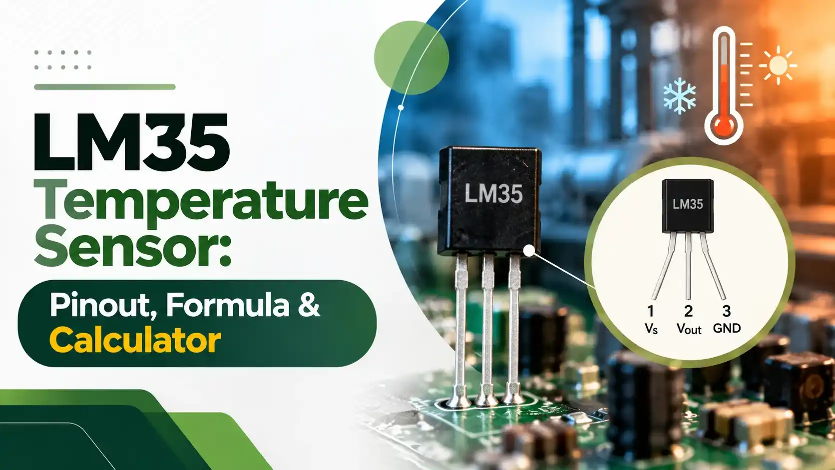
What Is the LM35 Temperature Sensor?
The LM35 temperature sensor is a precision integrated circuit whose output voltage rises linearly by 10 mV for every 1 °C, so 250 mV means 25 °C. It needs no external calibration, draws less than 60 µA and runs from any supply between 4 V and 30 V.
- Output: 10 mV per °C, 0 V at 0 °C, so T (°C) = Vout in mV ÷ 10.
- Pinout (flat face towards you): pin 1 +Vs, pin 2 Vout, pin 3 GND.
- Range: minus 55 °C to 150 °C for LM35 and LM35A; 0 °C to 100 °C for LM35D.
- Accuracy: ±0.5 °C at 25 °C for the A grade and ±1 °C for the standard part.
- Arduino Uno: T = reading × 500 ÷ 1024 with the default 5 V reference.
Texas Instruments, the maker, describes it as a centigrade sensor because its output is already scaled in Celsius, unlike Kelvin sensors that need an offset subtracted. Inside, it is a bandgap circuit, the same principle used in a precision reference voltage chip, trimmed at the wafer level.
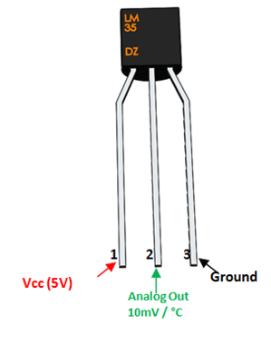
The labelled diagram shows the common TO 92 plastic package seen in every Indian electronics shop and college lab kit. Components101 lists pin 1 as Vcc, pin 2 as the analog output and pin 3 as ground, with ±0.5 °C accuracy and a minus 55 °C to 150 °C range.
LM35 Temperature Sensor Pinout and Connection
Hold the LM35 temperature sensor with the flat printed face towards you and the legs pointing down. From left to right the pins are +Vs, Vout and GND, and this order is the same for the TO 92 and TO 220 packages.
| Pin | Name | Connect To | Note |
|---|---|---|---|
| 1 | +Vs | 5 V pin of Arduino | 4 V to 30 V allowed |
| 2 | Vout | A0 analog input | 10 mV per °C |
| 3 | GND | Arduino GND | Common ground with ADC |
Before applying power, check the pin order twice, because a reversed LM35 gets hot within seconds and can be damaged. Touching the body gently after power up is a quick field check.
How the LM35 Temperature Sensor Works
Every silicon junction has a base emitter voltage that falls by roughly 2 mV per °C, while the difference between two junctions run at different current densities rises with absolute temperature. The LM35 combines these signals with an internal amplifier, much like an op amp stage, to produce a clean 10 mV per °C output.
Because the output is linear, there is no lookup table as with an NTC thermistor and no cold junction compensation as with a thermocouple. TI specifies typical nonlinearity of only ±0.3 °C for the standard grade.
The LM35 output impedance is only about 0.1 Ω at 1 mA, so it can drive an ADC input directly. TI says it can drive 50 pF without special precautions, but a long cable needs extra care.
LM35 Grades and Accuracy
TI sells several grades of the same die, each tested to a different limit. The table below uses the tested limits from the TI datasheet SNIS159H, so you can choose a grade before buying.
| Grade | Range | Accuracy at 25 °C | Full Range Accuracy |
|---|---|---|---|
| LM35A | minus 55 to 150 °C | ±0.5 °C | ±1 °C |
| LM35 | minus 55 to 150 °C | ±1 °C | ±1.5 °C |
| LM35CA | minus 40 to 110 °C | ±0.5 °C | ±1 °C |
| LM35C | minus 40 to 110 °C | ±1 °C | ±1.5 °C |
| LM35D | 0 to 100 °C | ±1.5 °C | ±2 °C |
Most hobby modules in India use the LM35DZ version of the LM35 temperature sensor. It is ideal for room, panel and liquid temperatures between 0 °C and 100 °C, but it cannot report below zero.
LM35 Temperature Sensor Arduino Formula
An Arduino Uno has a 10 bit ADC that converts 0 V to 5 V into a reading from 0 to 1023. Each step is 5 ÷ 1024 = 4.88 mV, or about 0.49 °C.
T (°C) = Vout (mV) ÷ 10
Short form for 5 V: T = reading × 500 ÷ 1024
Solved example: reading = 62, Vref = 5 V
Vout = 62 × 5000 ÷ 1024 = 302.7 mV
T = 302.7 ÷ 10 = 30.27 °C
T (°F) = 30.27 × 1.8 plus 32 = 86.49 °F
Some code divides by 1023 instead of 1024, and the difference is under 0.1 percent, far smaller than the sensor tolerance. In code, write float tempC = analogRead(A0) * 500.0 / 1024.0; and use a decimal point so the math is not done in integers.
LM35 Temperature Sensor Calculator
Second Solved Example: 1.1 V Internal Reference
With analogReference(INTERNAL) the ATmega328P on the Uno uses its internal 1.1 V reference. Each step is now 1.1 ÷ 1024 = 1.07 mV, so resolution improves to about 0.11 °C, while the usable range ends near 110 °C.
For a reading of 233, Vout = 233 × 1100 ÷ 1024 = 250.3 mV, which gives 25.03 °C. Because the internal reference can sit anywhere from about 1.0 V to 1.2 V on a given chip, measure it once at the AREF pin and use that value in your code.
Take 10 to 20 readings, discard the first one after switching the ADC reference and average the rest. This simple filter steadies the last digit on an LCD.
LM35 Temperature Sensor Negative Temperature Circuit
In the basic single supply circuit the LM35 temperature sensor output cannot go below ground, so it reads only from about 2 °C upwards. For the full minus 55 °C to 150 °C range, TI shows a resistor R1 from the output to a negative supply.
For a minus 5 V rail: R1 = 5 V ÷ 50 µA = 100 kΩ
Output: 1500 mV at 150 °C, 250 mV at 25 °C
Output: minus 550 mV at minus 55 °C
The ADC must then accept a bipolar input, so engineers usually add an offset and gain stage or use a sensor with a built in offset. Cold room and freezer projects in India often skip this effort and use a Pt100 RTD or a digital sensor instead.
LM35 vs Other Temperature Sensors
Celsius output at 10 mV per °C with zero volts at 0 °C.
Same idea scaled at 10 mV per °F.
Kelvin output at 10 mV per K, so 2.98 V at 25 °C.
500 mV offset at 0 °C lets a single supply read below zero.
For a wider view, see this guide to types of temperature sensors and the comparison of thermistor vs thermocouple.
The LM35 was originally introduced by National Semiconductor, which Texas Instruments acquired in 2011. That is why old datasheets and textbooks show the National logo on the same part.
Long Cable and Noise Tips
TI recommends a 0.1 µF bypass capacitor from +Vs to GND, placed close to the sensor, as explained in our guide on decoupling capacitors. For remote sensing it shows twisted pair wiring, so run the LM35 temperature sensor on a shielded twisted pair cable and ground the shield at one end only.
A long cable adds capacitance that can make the LM35 temperature sensor output stage oscillate. TI suggests a series damper of 75 Ω and 1 µF from output to ground, or a series resistor, and a simple RC low pass filter at the ADC pin removes most remaining hum.
Keep the sensor ground and the microcontroller ground at the same point to avoid ground loops.
Installation for Accurate Readings
TI notes that the leads should be kept at the same temperature as the surface, otherwise heat flowing along the copper causes temperature measurement errors.
LM35 Troubleshooting Table
| Symptom | Likely Cause | Fix |
|---|---|---|
| Reads about 500 °C | Vout shorted to 5 V or open ground | Check pin order and GND wire |
| Reads 0 °C always | Output open or wrong analog pin | Confirm A0 in code and wiring |
| Jumps by several degrees | Noise or long cable oscillation | Add 0.1 µF bypass and RC damper |
| Reads 2 to 5 °C high | Self heating in still air or warm board | Move away from regulator, reduce load |
| Sensor body very hot | Supply reversed | Power off and rewire |
- Linear Celsius output, no lookup table.
- Low current draw below 60 µA.
- Factory trimmed, no calibration needed.
- Low cost and easy to source in India.
- Needs at least 4 V supply.
- Negative temperatures need extra circuitry.
- Analog signal picks up noise on long cables.
- Not for industrial hazardous areas or high vibration.
Where the LM35 Is Used
In a fan controller, the sensor feeds an Arduino that drives a fan through PWM and a MOSFET. This is the same principle used in commercial electronic cooling fans.
TI LM35 Datasheet
LM35 Video Tutorial
LM35 Temperature Sensor FAQ
Divide the output voltage in millivolts by 10 to get the temperature in degrees Celsius. For example, 250 mV means 25 °C and 302 mV means about 30.2 degrees.
On an Arduino Uno with a 5 V reference, multiply the reading by 500 and divide by 1024. Always use floating point math so the result keeps its decimal places.
The output is 250 mV at 25 °C because the scale factor is 10 mV per degree. At 0 °C the output is zero volts in the basic circuit.
At 100 °C the output reaches 1 V, and at 150 °C it reaches 1.5 V on full range grades. This is why the output stays safely inside a 3.3 V or 5 V input range.
Yes, but only the full range grades and only with a resistor from the output to a negative supply. TI uses about 100 kΩ for a minus 5 V rail in its circuit.
The LM35D grade is rated only from 0 to 100 degrees. For freezers on a single supply, a sensor with a built in offset such as the TMP36 is often simpler.
The LM35 temperature sensor is an analog sensor that gives a voltage proportional to temperature. You need an ADC, a multimeter or a comparator to read it.
Digital sensors such as the DS18B20 or DHT11 send data as serial bits instead. The analog output of the LM35 makes it easy to test with a simple meter on the bench.
The LM35 measures only temperature and gives an analog voltage with about ±0.5 °C to ±1 °C accuracy at room temperature. It covers a much wider range than the DHT11 as well.
The DHT11 measures humidity and temperature together over a single digital wire. Its temperature accuracy is about ±2 °C and its range is roughly 0 to 50 degrees.
The usual causes are noise on a long cable, a missing bypass capacitor or a 5 V USB supply that is not exactly five volts. Wrong pin order and integer math in code also give strange values.
Add a 0.1 µF capacitor at the sensor and average several readings in software. Then compare the result with a reference thermometer at room temperature.
The sensor needs at least 4 V on its supply pin, so power it from the 5 V or VIN pin of the board. Its output stays below 1.5 V, which a 3.3 V ADC input can accept safely.
The ESP32 ADC is less linear than the Uno ADC near its ends. Calibrate it at two known temperatures or use an external ADC for better results.
Related Articles
- Types of Temperature Sensors
- NTC and PTC Thermistor Working
- ADC Working Principle Explained
- RTD Temperature Sensor Working
- Capacitive Humidity Sensor Working
External References
- LM35 Precision Centigrade Temperature Sensors Datasheet, Texas Instruments
- LM35 Pinout, Features and Datasheet, Components101
- Silicon Bandgap Temperature Sensor, Wikipedia
What We Learn Today
- The LM35 temperature sensor gives 10 mV per °C, so dividing the output in millivolts by 10 gives the temperature directly in degrees Celsius.
- On an Arduino Uno with a 5 V reference, temperature equals reading × 500 ÷ 1024, and the 1.1 V reference improves resolution to about 0.11 °C.
- Negative temperatures need a resistor to a negative supply, while long cables need a bypass capacitor, twisted pair wiring and an RC damper.
