
Two resistors, two capacitors and one op amp can produce a sine wave pure enough for audio testing. The secret is holding the amplifier gain at exactly three, and the way you do that decides how clean the output really is.
The Wien bridge oscillator is the classic low distortion sine wave source for audio and test work. This guide covers its frequency formula, the gain of three condition, amplitude stabilisation methods and a full design example.
What Is a Wien Bridge Oscillator?
A Wien bridge oscillator is a sine wave oscillator that uses a series RC and a parallel RC network as frequency selective positive feedback around a non inverting amplifier. At one frequency the network has zero phase shift and passes one third of the output back, so an amplifier gain of three keeps the oscillation going.
It is usually built with an operational amplifier, and it works best from a few hertz to a few hundred kilohertz. Students meet it alongside the other types of transistor oscillators, but it stands out for its low distortion and easy tuning.
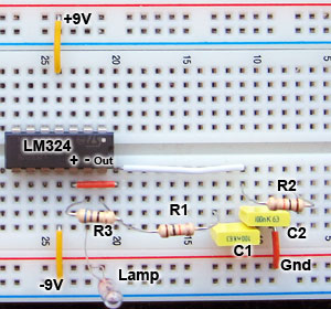
Learn About Electronics built a test circuit with 10 kΩ resistors and 100 nF capacitors. The calculated frequency was 159 Hz and the measured frequency was 157 Hz, which shows how closely the simple formula predicts a real circuit.
How the RC Bridge Selects One Frequency
The feedback path has a series R and C going to the non inverting input and a parallel R and C from that input to ground. At low frequency the series capacitor blocks the signal, and at high frequency the parallel capacitor shorts it, much like the two halves of an RC low pass and high pass filter placed back to back.
Exactly at the centre frequency the output of this band pass network is in phase with its input and equal to one third of it. Any other frequency gets both a phase error, explained in phase angle in AC circuits, and extra attenuation, so the loop cannot sustain it.
The second half of the bridge is the negative feedback divider RF and RG that sets the amplifier gain. Together the two arms form a bridge similar to the Wheatstone bridge, which is where the circuit gets its name.
Max Wien described his bridge in 1891 for measuring impedance, long before it became an oscillator. William Hewlett used it with a small lamp for amplitude control in the HP 200A audio oscillator, the first product of Hewlett Packard.
Wien Bridge Oscillator Frequency Formula
When both resistors are equal to R and both capacitors are equal to C, the frequency and gain conditions become very simple. Texas Instruments engineers Ron Mancini and Richard Palmer state the requirement as an amplifier gain A of 3, with RF equal to twice RG.
Gain = 1 + RF ÷ RG = 3, so RF = 2 × RG
Example:
R = 10 kΩ, C = 10 nF, RG = 10 kΩ
R × C = 10000 × 0.00000001 = 0.0001 s
f0 = 1 ÷ (6.2832 × 0.0001) = 1591.5 Hz
f0 = 1.59 kHz, RF = 20 kΩ
The TI application report used similar values and calculated 1.59 kHz, while the built circuit oscillated at 1.57 kHz. Component tolerance and op amp phase shift explain the small difference, so always trim the final frequency on the bench.
Wien Bridge Oscillator Calculator
Enter R in kilohms and C in nanofarads, since kΩ times nF gives microseconds. In practice RF is made slightly larger than twice RG so that oscillation starts reliably, and a stabiliser then pulls the gain back to three.
Why the Gain Must Be Exactly Three
If the loop gain is even slightly below one, the oscillation dies away. If it is slightly above one, the amplitude keeps growing until the op amp output hits the supply rails, which flattens the peaks and adds harmonics, the problem described in harmonic distortion and THD.
The TI report shows that a plain circuit without any gain control had about 2.8 percent distortion, mainly from clipping at the rails. Fixed resistors alone can never hold the gain at exactly three, because they drift with temperature and age.
The answer is a nonlinear or automatic gain control element that lowers the gain as the amplitude rises. This is the same loop gain idea studied with a Bode plot and gain margin, except that here we want the loop to sit right at the edge.
Use film or C0G ceramic capacitors and 1 percent metal film resistors in the bridge. Ordinary high K ceramic capacitors change value with voltage and add distortion of their own.
Amplitude Stabilisation Methods Compared
A small lamp replaces RG, and its resistance rises as it warms, cutting the gain.
A thermistor replaces RF, and its resistance falls as it heats.
Back to back diodes across part of RF reduce gain on the peaks.
A rectified output sets the gate voltage, and the JFET acts as a variable resistor.
The lamp and the NTC thermistor respond to the average power over many cycles, so they barely change within one cycle. That is why they produce very little distortion, and TI measured less than 0.1 percent at 1.57 kHz with a lamp.
The diode method changes gain within each cycle, which slightly bends the peaks of the sine wave. A Zener diode in series can also limit the swing, giving a simple design with moderate distortion and no warm up delay.
The JFET method rectifies the output, stores the peak on a capacitor and drives the JFET gate, so the channel resistance trims the gain. TI reports distortion below 0.2 percent with this approach, and the loop settles faster than a lamp.
Elliott Sound Products describes a lamp that measures about 10 Ω cold and about 100 Ω when hot at 6 V. Learn About Electronics advises a lamp rated around 50 mA or less, so the small output current of an op amp can heat it.
5 Steps to Design a Wien Bridge Oscillator
Choose an op amp whose gain bandwidth and slew rate are well above what the output frequency and amplitude need. For tuning, a dual gang potentiometer changes both R values together, while switched capacitors change the decade.
Second Worked Example: A 1 kHz Test Oscillator
Suppose you need a 1 kHz source for checking audio amplifiers and you choose C = 10 nF. Then R = 1 ÷ (2π × 1000 × 0.00000001), which is 15915 Ω, and the nearest E24 value is 16 kΩ.
With 16 kΩ the frequency becomes 1 ÷ (2π × 16000 × 0.00000001), about 995 Hz, which is within 0.5 percent of the target. For the gain network, a 10 kΩ RG with RF made from 20 kΩ plus a small trim resistor gives a clean start.
Check the Wien bridge oscillator output on a cathode ray oscilloscope and adjust the trim until the wave just stops clipping. A well tuned Wien bridge oscillator should show smooth rounded peaks with no flat tops.
A lamp based Wien bridge oscillator takes a short time to settle after power on or a frequency change, because the filament must warm up. That slow response is also what keeps its distortion so low.
- Very low distortion with good amplitude control.
- Simple design with one op amp and a few parts.
- Easy tuning with a dual potentiometer.
- Wide audio and low frequency range.
- Needs an amplitude stabilising element.
- Lamp and thermistor versions settle slowly.
- Not ideal for very high radio frequencies.
- Frequency stability lower than a crystal oscillator.
If the output slowly bounces up and down in amplitude after power on, the stabiliser loop is too slow or the gain margin is too large. Reduce the excess gain or shorten the AGC time constant a little.
Commissioning and Troubleshooting Checklist
- Confirm the two bridge resistors and capacitors are matched.
- Measure the frequency with a counter or oscilloscope.
- Check that the peaks are rounded and not clipped.
- Verify the lamp or thermistor is warm and stable.
- Check supply decoupling close to the op amp pins.
- Measure distortion with an audio analyser where available.
- Confirm the output stays stable across temperature changes.
If a Wien bridge oscillator will not start, the gain is below three, so increase RF slightly. If it clips, reduce excess gain or check the stabiliser, and compare its behaviour with a crystal oscillator when you need tight frequency accuracy instead of low distortion.
Where Wien Bridge Circuits Are Used
For square and triangle waves, a 555 timer IC is simpler, but it cannot give a clean sine. Active filter designs such as the Sallen and Key filter use the same RC and op amp skills.
TI Sine Wave Oscillator Application Report
Wien Bridge Oscillator Video Lesson
Wien Bridge Oscillator FAQ
It is a sine wave oscillator that uses a series RC and a parallel RC network as positive feedback around an amplifier. At one frequency the network gives zero phase shift and one third attenuation.
An amplifier gain of three then sustains a steady oscillation. The circuit is popular for audio and test work because its distortion can be very low.
With equal resistors R and equal capacitors C, the frequency is 1 divided by 2π times the RC product. For 10 kΩ and 10 nF this gives a frequency of about 1591 hertz.
Unequal parts make the formula more complex and also change the required gain. Most practical designs therefore keep the two arms matched.
The RC network passes back exactly one third of the output at the centre frequency. A gain of three makes the total loop gain equal to one, which keeps the amplitude constant.
Lower gain lets the oscillation die out, while higher gain drives the output into clipping. A stabiliser holds the gain right at the required value.
A small lamp in place of RG has a resistance that rises as the filament warms. Higher output warms it more, which lowers the gain and holds the amplitude steady over time.
Because the filament responds to average power, it does not distort individual cycles. TI measured distortion below 0.1 percent with a lamp stabilised design.
Yes, back to back diodes across part of RF reduce the gain whenever the peaks become large. This is cheap, compact and needs no warm up time at all.
The drawback is that the diodes act within every cycle, so they bend the peaks slightly. Expect higher distortion than with a lamp or a JFET loop.
The output is rectified and stored on a capacitor, and that voltage drives the gate of a JFET transistor. The channel then acts as a variable resistor in the gain network.
When amplitude rises, the channel resistance changes to reduce the gain. TI reports distortion below 0.2 percent with this automatic gain control method in a Wien bridge oscillator.
It works well from a few hertz up to a few hundred kilohertz with a good op amp. Very low frequencies need large capacitors, which are bulky and harder to match.
At higher frequencies the op amp bandwidth and slew rate add phase shift and distortion. LC or crystal circuits are better choices for radio frequency work.
Related Articles
- Operational Amplifier Op Amp Basics
- Types of Transistor Oscillators
- Crystal Oscillator Working Principle
- RC Low Pass and High Pass Filter
- NTC and PTC Thermistor Working
External References
- Sine Wave Oscillator, Texas Instruments Application Report SLOA060
- Wien Bridge Oscillators, Learn About Electronics
- Wien Bridge Oscillator, Wikipedia
What We Learn Today
- A Wien bridge oscillator runs at f0 = 1/(2πRC), so 10 kΩ and 10 nF give about 1.59 kHz with an op amp gain of three.
- The gain must stay at exactly three, which needs a lamp, thermistor, diode limiter or JFET loop to control the output amplitude automatically.
- Texas Instruments measured about 2.8 percent distortion with no gain control, below 0.1 percent with a lamp and below 0.2 percent with a JFET.
