
A thin corrugated metal disc clamped between two flanges can read pressures as low as a few millibar and still survive many times its full scale. That combination makes it the gauge of choice for low pressure, corrosive and viscous process media.
When a Bourdon tube is too weak, too easily clogged or too easily corroded, a diaphragm element is usually the answer. Here is how it works, what its limits are and how to select one that lasts.

What Is a Diaphragm Pressure Gauge?
A diaphragm pressure gauge is a mechanical gauge whose sensing element is a circular, corrugated metal diaphragm clamped between an upper and a lower flange. Process pressure deflects the diaphragm, and a push rod and movement turn that small deflection into pointer rotation, just as the tube does in a Bourdon tube pressure gauge.
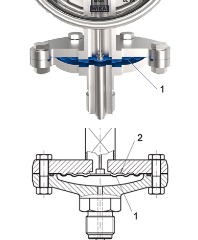
Because the diaphragm has a large area, a small pressure produces a usable force. That is why the design covers low ranges in millibar and remains common wherever the medium would corrode, clog or crystallise inside a thin tube, a topic also touched on in basics of pressure measurement.
Inside the Gauge: Parts and Construction
Thin disc with concentric waves that flexes in proportion to pressure.
Clamp the diaphragm and form the process chamber below it.
Transfer the centre deflection to a geared movement.
Stainless case, often with blow out back or solid baffle wall.
WIKA explains that the concentric waves allow a diaphragm travel of about 1 to 3 mm, which is enough for a mechanical movement and gives good linearity. A flat disc without waves would give a much less linear response.
The lower flange is the only part wetted by the process in most designs, which keeps the instrument simple to protect. For extra isolation, the same gauge can sit on a diaphragm seal with a fill fluid between the process and the element.
How a Diaphragm Pressure Gauge Works
The reading is gauge pressure, referenced to the atmosphere above the diaphragm, as explained in absolute vs gauge pressure. Vacuum and compound ranges are also made, because the diaphragm can deflect downward as well as upward.
WIKA notes that its diaphragm gauges can measure ranges as low as 16 mbar, about 6 inches of water column. A standard Bourdon tube gauge struggles below about 0.6 bar.
Why the Diaphragm Survives Overload
When pressure goes above full scale, the diaphragm simply rests against a matching contoured bed in the upper flange. The large contact area spreads the load, so the element does not take a permanent set.
WIKA states that its diaphragm pressure gauge has a standard overload safety of five times the full scale value, against about 1.3 times for a Bourdon tube. Special models reach 400 bar overload even on a 0 to 16 mbar range, a far better result than the add on devices in pressure gauge over range protection.
This makes the design a natural choice for low range points that may see a blocked line or a pump start. Pressure pulsation is a separate problem, and a pressure snubber is still useful when the pointer flutters.
Accuracy and Overload Formula
Under EN 837 3, the accuracy class is the maximum permissible error as a percentage of the span. The overload limit is simply the overload factor times the full scale value.
Overload limit = Overload factor × Full scale
Example:
Range 0 to 100 mbar, class 1.6, overload factor 5, worst process peak 300 mbar
Error = 1.6 ÷ 100 × 100 = ±1.60 mbar
Overload limit = 5 × 100 = 500 mbar
300 mbar is below 500 mbar, so the peak is within the overload limit
Accuracy classes are compared in more detail in pressure gauge accuracy classes. Remember that the class error applies across the whole span, so a reading near the bottom of the scale has a much larger relative error.
Diaphragm Pressure Gauge Calculator
Second Worked Example: Blower Discharge Point
A combustion air blower runs at about 40 mbar, but a closed damper can push the line to 250 mbar for a short time. A Bourdon tube is not practical at such a low range, so a diaphragm element is the obvious choice.
A 0 to 60 mbar class 1.6 gauge puts the normal reading at two thirds of scale with an error of ±0.96 mbar. With a five times overload rating its limit is 300 mbar, so the 250 mbar upset is survived without any extra protection.
Choose the range so that the normal reading falls between about one third and two thirds of the scale. The WIKA PM 04.03 datasheet allows steady load up to full scale and fluctuating load up to 0.9 times full scale, but the middle of the dial is easier to read and gentler on the element.
Diaphragm vs Bourdon Tube vs Capsule
| Feature | Diaphragm | Bourdon Tube | Capsule |
|---|---|---|---|
| Typical ranges | 16 mbar to 25 bar | 0.6 bar to 1000 bar and above | A few mbar to about 600 mbar |
| Overload safety | About 5 × full scale | About 1.3 × full scale | Low unless protected |
| Liquids and slurries | Very good | Fair, may clog | Gas only |
| Corrosion protection | Linings and special diaphragm metals | Limited to tube alloy | Limited |
| Size and weight | Larger, heavier | Compact | Compact |
Capsule gauges use two diaphragms welded together and suit dry gases only, so they are not a replacement for a process diaphragm gauge. A differential pressure gauge uses a similar element with pressure on both sides when you need a difference instead of a single pressure.
6 Simple Steps to Select the Right Gauge
This sequence follows the general method in pressure gauge selection factors, with extra weight on overload and wetted materials. Filling liquid matters when the gauge sits on pumps or compressors, as discussed in hammer effect in pressure gauges.
Corrosive, Viscous and Hygienic Media
WIKA lists diaphragm materials such as tantalum, titanium, gold, platinum and Hastelloy, plus PTFE linings for the lower flange. Threaded ½ NPT connections cannot be lined, but an open flange connection such as 1 inch class 150 to ASME B16.5 can be.
For viscous, crystallising or contaminated media, an open flange of 1 inch or 2 inch nominal width gives a wide chamber that resists clogging, and the lower flange can carry flushing ports. In food and pharma plants the diaphragm is welded flush with the process connection, a practice explained in flush connections in sanitary measurement.
WIKA offers a diaphragm monitoring design with two diaphragms in series that warns the operator if the outer one is breached. It lets a hygienic plant detect a leak before product reaches the instrument.
- Reads low ranges down to about 16 mbar.
- About 5 times overload safety as standard.
- Wide choice of linings and exotic diaphragm metals.
- Open flange designs resist clogging.
- Can be cleaned and flushed in service.
- Larger and heavier than a Bourdon gauge.
- Upper range limited to about 25 bar on standard models.
- Flange joint adds a possible leak point.
- Higher cost, especially with special linings.
- Lined versions are usually class 2.5 rather than 1.6.
Installation and Maintenance Checklist
- Mount the gauge vertically with the dial upright unless the datasheet allows otherwise.
- Fit an isolation valve so the gauge can be removed in service.
- Support heavy flanged gauges, do not hang them on small tubing.
- Use a siphon on steam and hot condensate service.
- Torque flange bolts evenly to protect the diaphragm seal.
- Flush viscous or crystallising media through the flushing ports.
- Check zero with the line isolated and vented.
- Calibrate at the interval in the datasheet, often one year.
Many failures come from simple fitting errors, so review pressure gauge installation mistakes before commissioning. On steam service, a siphon tube keeps the element away from live steam temperatures.
For calibration, a comparison against a reference gauge or a dead weight pressure tester at five points rising and falling is normal practice. Record any hysteresis, since a fatigued or damaged diaphragm shows it before it fails completely.
EN 837 3 and Key Datasheet Values
EN 837 3 is the European standard for diaphragm and capsule pressure gauges, while EN 837 1 covers Bourdon tube gauges. The WIKA PM 04.03 datasheet for the process models 432.50 and 433.50 lists nominal sizes of 100 and 160 mm and accuracy class 1.6, or 2.5 with a lining.
The same datasheet gives ranges from 0 to 16 mbar up to 0 to 25 bar, a temperature error of up to 0.8 percent of full scale per 10 °C, and medium temperature up to 100 °C or 200 °C. Diaphragms are 316L for spans up to 0.25 bar and a nickel chromium alloy for spans from 0.4 bar.
When a diaphragm pressure gauge on an outdoor tank reads differently at noon and dawn, check the temperature error before you suspect the element. At 0.8 percent per 10 °C, a 30 °C swing can move the reading by about 2.4 percent of full scale.
WIKA Data Sheet PM 04.03
Diaphragm Gauge Animation
Diaphragm Pressure Gauge FAQ
It is a mechanical gauge that senses pressure with a corrugated metal diaphragm clamped between two flanges. The deflection of the diaphragm drives a push rod, a movement and a pointer.
It suits low ranges, overload prone points and difficult media. It is built to EN 837 3 and is widely used in chemical, water and food plants.
WIKA lists full scale ranges starting at 0 to 16 mbar, which is about 6 inches of water column. That is far below the practical lower limit of a Bourdon tube.
Very low ranges use a large diaphragm and a carefully machined support bed. The same design keeps the element safe when the pressure rises well above full scale.
Above full scale, the diaphragm rests firmly against a contoured bed machined into the upper flange. The load spreads over a large area, so the metal is not permanently bent.
WIKA quotes five times full scale as standard and up to ten times on request. Special designs reach 400 bar even on very low ranges.
Yes, because only the lower flange and the diaphragm touch the process fluid. These parts can be made from tantalum, titanium, Hastelloy or gold, or given a PTFE lining.
Linings require an open flange process connection rather than a thread. A lined gauge is usually supplied in accuracy class 2.5 instead of the normal class 1.6.
A capsule is made of two diaphragms welded together at the rim. It suits only clean and dry gases at very low pressure, such as fuel gas or air.
A diaphragm gauge has a single element with a wide open chamber below it. It therefore works with liquids, slurries and corrosive media that a capsule cannot handle.
Class 1.6 is the usual choice for process diaphragm gauges on 100 or 160 mm dials. Lined versions are normally class 2.5 because the lining slightly stiffens the element.
Use the permissible error formula to see what the class means in mbar or bar. Then choose a range that keeps the normal reading near mid scale for the best readability.
The WIKA PM 04.03 datasheet recommends a calibration interval of one year for these instruments. Plant procedures may shorten that for critical or harsh duty points.
Check at five points, rising and falling, against a reference gauge or dead weight tester. Record hysteresis and zero shift carefully, since both reveal a tired or damaged diaphragm.
Related Articles
- Bourdon Tube Pressure Gauges
- Pressure Gauge Accuracy Classes
- What Is a Diaphragm Seal
- Pressure Gauge Over Range Protection
- Differential Pressure Gauge Working
External References
- Diaphragm Pressure Gauge for the Process Industry, WIKA Data Sheet PM 04.03
- Three Reasons to Use a Diaphragm Pressure Gauge, WIKA Blog
- Pressure Measurement, Wikipedia
What We Learn Today
- A diaphragm pressure gauge senses pressure with a corrugated disc between two flanges, and its 1 to 3 mm travel drives a mechanical movement.
- The diaphragm rests on a contoured bed when overloaded, giving about five times full scale overload safety against roughly 1.3 times for Bourdon tubes.
- Open flanges, PTFE linings and tantalum or Hastelloy diaphragms make it suitable for low mbar ranges and corrosive, viscous or crystallising media.
