
A closed vessel pushes its vapour pressure onto both sides of a DP transmitter, and the way you connect the low side decides whether that pressure cancels cleanly. Choosing between a dry or filled reference line, and ranging it correctly, is the heart of reliable DP level.
A wet leg is a reference line filled with a stable liquid that connects the vessel top to the low side of a DP level transmitter. It removes condensation errors but needs zero elevation, careful fill fluid choice and a correct LRV and URV calculation.
What Is a Wet Leg in DP Level Measurement?
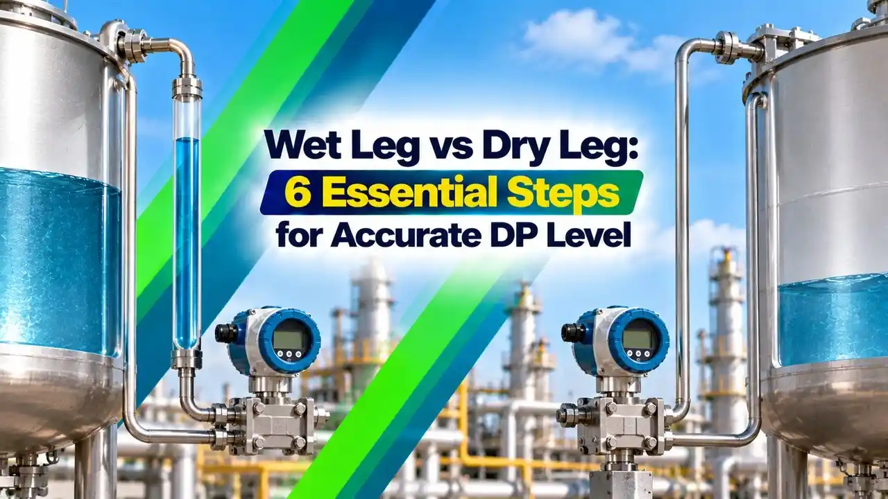
A wet leg is the low pressure impulse line of a closed tank DP level transmitter, deliberately kept full of liquid from the upper vessel tap down to the transmitter. A dry leg is the same line kept full of gas or vapour, as introduced in DP transmitter level measurement.
In a closed vessel, the gas pressure above the liquid acts on both taps. Connecting the upper tap to the low side of a differential pressure transmitter subtracts that pressure, so only the liquid head remains.
Control Global, in an article by contributing editor Paul Miller, explains that dry legs suit non condensing vapour spaces while filled reference legs handle vapours that may condense. The same article quotes an instrumentation specialist who calls DP perhaps the most simple and reliable technology for measuring level as well as flow.
The reading of a filled reference line runs backwards compared with a dry leg. The DP is most negative when the tank is empty and rises toward zero as the tank fills.
How a Dry Leg Works
In a dry leg, the high side senses vapour pressure plus liquid head while the low side senses vapour pressure alone. The two vapour pressures cancel, so DP equals level times specific gravity, plus any head below the lower tap.
The method works only while the line stays dry. CANTEACH training notes from the CANDU nuclear industry explain that condensable vapour such as steam forms condensate in the low side line, which then needs a knock out pot and frequent draining, much like a condensate pot in steam applications.
On a dry leg, slope the line continuously back toward the vessel so any condensate drains away by itself. A single sag can trap liquid and shift the zero without warning.
How a Wet Leg Works
In this arrangement, the low side line is filled completely with liquid, either the condensed process vapour or a separate seal fluid. Its head is constant, so it can be subtracted during ranging, which is called zero elevation in zero elevation and zero suppression.
Because the leg head is larger than the level head, the DP stays negative across the range. Steam drums use this arrangement, as described in boiler drum level control, because steam condenses and keeps the leg naturally full.
Control Engineering, in an article by Chris Hardy of Cross Company, notes that water at 580 °F, about 304 °C, is only 73 percent as dense as water at 100 °F. He also states that the condensing pot must not be insulated, since insulation stops the condensation that keeps the leg full.
Wet Leg vs Dry Leg Comparison
| Feature | Dry Leg | Wet Leg |
|---|---|---|
| Low side line contents | Gas or vapour | Liquid, condensate or seal fluid |
| Vapour type suited | Non condensing | Condensing, such as steam |
| Ranging | Zero suppression or true zero | Zero elevation, LRV negative |
| Main error source | Condensate collecting in line | Leg losing fluid or changing density |
| Maintenance | Drain knock out pot | Refill and check leg level |
The same choice appears on vessels with remote seals, where a capillary filled with oil acts as a sealed wet leg. Fill fluid choice is covered in fill fluid selection for diaphragm seals, and capillary routing rules appear in capillary tubing in pressure measurements.
Choosing the Fill Fluid for a Wet Leg
Vapour condenses in a pot and keeps the leg full automatically.
Lower freezing point for outdoor legs.
Stable density over a wide temperature range.
Immiscible liquid that protects the transmitter.
The fill must not mix with or dissolve into the process, and its specific gravity must stay stable, as explained in what is specific gravity. A seal pot at the top lets you top up the leg and see its level.
If a filled leg slowly loses fluid, the DP rises and the indicated level climbs even though the tank is unchanged. Operators then see a high level that does not exist.
6 Essential Steps to Calculate LRV and URV
LRV = e × SGp minus (H + e) × SGw
URV = (H + e) × SGp minus (H + e) × SGw
Heads in mm of water column
Example:
H = 3 m, e = 0.5 m, SGp = 0.95, SGw = 1.0
LRV = 0.5 × 0.95 minus 3.5 × 1.0 = 0.475 minus 3.5 = minus 3.025 m
URV = 3.5 × 0.95 minus 3.5 = 3.325 minus 3.5 = minus 0.175 m
LRV = minus 3025 mmH2O, URV = minus 175 mmH2O, span = 2850 mmH2O
The span always equals the tap spacing times the process specific gravity, whatever the leg type. A complete range worksheet is given in how to calculate the range for DP level transmitters.
Wet Leg LRV and URV Calculator
Multiply mmH2O by 0.00980665 to get kPa, so the example gives an LRV of about minus 29.67 kPa and a URV of about minus 1.72 kPa. Many HART transmitters accept the range directly in mmH2O, which avoids rounding errors.
Second Worked Example: Same Tank With a Dry Leg
Keep H = 3 m, e = 0.5 m and SGp = 0.95, but now the low side line is dry. The low side head is zero, so LRV = 0.5 × 0.95 = 475 mmH2O and URV = 3.5 × 0.95 = 3325 mmH2O.
Here the LRV is positive, which is called zero suppression, and the span is again 2850 mmH2O. The procedure for checking such a range on the bench is described in DP level transmitter calibration.
Before ranging any filled leg transmitter, open the equalising valve on the manifold and confirm a true zero. Then close it and fill the leg slowly to avoid trapped air.
Installation Rules for a Wet Leg System
Mount the transmitter below the lower tap so both lines stay full of liquid and gas bubbles rise back into the vessel. Slope all impulse lines at least as recommended in impulse line installation slope, and fit a 3 valve or 5 valve manifold for isolation and equalising.
Outdoor legs in cold regions need protection against freezing, either by glycol fill or by heat tracing in piping systems. Tracing must be gentle and even, since heating one leg more than the other changes its density and shifts the zero.
- Condensing or seal pot fitted at the upper tap, level with or above it.
- Condensing pot left uninsulated on steam service.
- Leg filled completely, with vents opened to remove air.
- Fill fluid specific gravity recorded on the datasheet.
- LRV and URV entered with the correct negative signs.
- Both impulse lines routed together at the same temperature.
- Leg level checked during routine maintenance.
Errors and Troubleshooting
If the level reads high and steady after a maintenance job, suspect a partly drained leg that was not refilled. If it drifts with ambient temperature, check whether the leg and process side see different heating, a problem similar to the one in remote seal temperature effect.
Steam drums add another error, because the density of the hot water inside the drum differs from the cool water in the leg. Control Engineering shows that an uncompensated drum full of 304 °C water can register over 13 inches of DP when it should read zero, which is why density compensation as in DP level measurement with varying density is essential.
- Handles condensing vapours such as steam.
- Constant reference head, easy to compensate.
- No condensate traps to drain daily.
- Works with standard DP transmitters.
- Leg can lose fluid and shift the zero.
- Fill density changes with temperature.
- Needs freeze protection outdoors.
- Ranging with negative values confuses new technicians.
Where Each Arrangement Fits
Where the leg itself becomes a maintenance burden, many plants move to capillary seals, electronic remote seals or a different principle altogether, such as guided wave radar. The basic hydrostatic method is reviewed in hydrostatic level measurement.
CANTEACH Level Instrumentation Notes
Rosemount DP Level Video
Wet Leg FAQ
It is the low side impulse line of a closed tank DP level transmitter that is kept full of liquid. The liquid may be condensed process vapour or a separate seal fluid.
Its head is constant, so it can be removed during ranging. This lets the transmitter measure level even when the vapour space keeps condensing.
Use a dry leg when the vapour above the liquid does not condense at the operating and ambient temperatures. Nitrogen or air blanketed tanks are common examples.
The low side line must stay free of liquid at all times. Slope it back toward the vessel and fit a knock out pot if small amounts of condensate can appear.
At zero level the low side sees the full head of the filled leg, while the high side sees almost nothing. The differential pressure is therefore negative.
As the tank fills, the high side head rises and the DP climbs toward zero. Setting a negative LRV in this way is called zero elevation in level work.
Write the high side head as level plus elevation times process gravity, and the low side head as tap spacing plus elevation times fill gravity. Subtract the low side from the high side.
For H = 3 m, e = 0.5 m, SG 0.95 and fill SG 1.0, the LRV is minus 3025 mmH2O for this tank. The URV is minus 175 mmH2O, giving a span of 2850 mmH2O across the range.
The pot works by cooling steam until it condenses and keeps the leg topped up. Insulation keeps the pot hot and stops this condensation.
Control Engineering makes the same point for steam drum installations. It also advises a pipe of at least 1 inch from the drum to the pot and tubing that slopes down to the transmitter.
Process condensate is the simplest choice on steam service because it refills the line by itself. Glycol water mixtures protect outdoor legs against freezing during the winter months.
Silicone oil or another stable liquid suits sealed systems and capillaries. The fluid must not mix with the process, and its density must be known accurately at the operating temperature.
The most common cause is fluid loss from the leg through leaks, venting or evaporation. A partly empty leg makes the indicated level read too high.
Temperature differences between the leg and the vessel also change density and shift the zero. Check the leg level, refill it and route both lines together at similar temperature.
Related Articles
- DP Transmitter Level Measurement
- Zero Elevation and Zero Suppression
- Condensate Pot in Steam Applications
- Boiler Drum Level Control
- DP Level Transmitter Calibration
External References
- Level Instrumentation Training Notes, CANTEACH
- Density Compensation for Steam Drum Levels, Control Engineering
- Pressure Measurement, Wikipedia
What We Learn Today
- A dry leg suits non condensing vapour, while a wet leg keeps the low side line full of liquid so condensing vapours such as steam cause no error.
- For a filled leg, LRV = e × SGp minus (H + e) × SGw, so the range is negative and the span still equals H × SGp.
- Reliable installations use an uninsulated condensing pot, a stable fill fluid, sloped lines, freeze protection and regular checks of the leg level.