
A controller acting on a broken measurement can drive a valve fully open in seconds and push a unit into a trip or worse. Every DCS therefore checks the quality of each process value and decides what the loop, the alarm and the interlock should do when that value cannot be trusted.
A failed transmitter does not just give a wrong number, it can mislead a control loop and an interlock at the same time. Learn how a DCS detects a bad process value and how loops, alarms and voting logic should respond.
What Is Bad PV Handling?
Bad PV handling is the set of DCS rules that detect when a process variable can no longer be trusted and then decide how control loops, alarms and interlocks react to it. It starts at the input card, where a broken wire or a failed transmitter on a 4 to 20 mA current loop first shows up.
Every value in a modern DCS carries a status along with its number. The status flows through the function blocks described in DCS function block programming, so a downstream PID block knows whether its input is healthy.
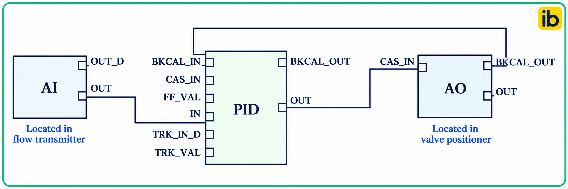
The Control.com fieldbus textbook explains that blocks can be programmed to switch mode when a Bad or Uncertain input status is detected. The same source notes that a Bad status propagates downstream, so no block acts on data it should not trust.
Good, Uncertain and Bad Signal Status
The value is valid and within its configured range, and the device reports no fault.
The value may be usable but has lower confidence, such as a reading beyond range or a sensor near its limits.
The device, wiring or card has a detected fault, so the number must not drive control.
FOUNDATION Fieldbus, HART devices and OPC servers all use this three level idea, with substatus codes such as sensor failure, device failure, out of service or last usable value. The KMITL fieldbus paper states that devices separate serious problems as Bad and less serious ones as Uncertain, a scheme also used in FOUNDATION Fieldbus.
For plain analog signals, bad PV handling begins at the DCS input card, which assigns the status itself from the current level and its own diagnostics. HART devices add more detail through device status bits, as explained in how the HART protocol works.
NAMUR NE 107 groups device diagnostics into four signals: Failure, Function Check, Out of Specification and Maintenance Required. A DCS can map Failure to Bad and Out of Specification to Uncertain for each process value.
NAMUR NE 43 Limits for 4 to 20 mA
NAMUR NE 43 lets the input card tell a real measurement from a failure signal. A transmitter keeps its measuring signal between 3.8 and 20.5 mA, and drives 3.6 mA or less, or 21 mA or more, when it detects an internal fault, as covered in NAMUR NE 43 standard explained.
| Loop Current | Meaning | Status in DCS |
|---|---|---|
| 3.6 mA or less | Transmitter failure, downscale | Bad |
| 3.6 to 3.8 mA | Below measuring range, not yet failure | Uncertain |
| 3.8 to 20.5 mA | Valid measurement including slight over range | Good |
| 20.5 to 21 mA | Above saturation, not yet failure | Uncertain |
| 21 mA or more | Transmitter failure, upscale | Bad |
| Near 0 mA | Open wire or lost loop power | Bad |
Whether a transmitter fails high or low is a configuration choice. Temperature transmitters call this burnout direction, described in burnout function in temperature transmitters, and it should match what makes the process safer.
During loop checks, use a HART communicator to force 3.5 mA and 22 mA from the transmitter. Confirm the DCS shows Bad status and raises the right alarm before you sign the loop sheet.
NE 43 Status and PV Calculator
This calculator converts a loop current into engineering units and classifies its status using the NE 43 bands. It helps when deciding which band a reading falls in during loop checks or troubleshooting.
Percent of span = (mA minus 4) ÷ 16 × 100
Example: 20.8 mA on a 0 to 200 °C range
PV = 0 + 16.8 ÷ 16 × 200 = 210.00 °C
Percent = 16.8 ÷ 16 × 100 = 105.0 %
20.8 mA lies between 20.5 and 21 mA, so status is Uncertain
At 3.7 mA the same range gives minus 3.75 °C with Uncertain status, a common sign of a drifting transmitter or a leaking cable. Values outside the measuring band should be investigated even when they are not yet marked Bad.
How a PID Loop Reacts: Mode Shedding
When the PV of a PID block turns Bad, the usual bad PV handling action on most DCS platforms is to shed the loop from AUTO or CASCADE to MANUAL, or to an initialisation manual mode, and freeze the output. The available modes are explained in DCS control modes.
In a cascade, a Bad secondary PV also breaks the outer loop, which must stop integrating and track its output. The structure of such loops is described in cascade control.
The KMITL paper on FOUNDATION Fieldbus cascade control describes a further option, where the PID passes a Bad status to the AO block. That forces the AO fault state and drives the valve to its configured safe position because control cannot continue without a measurement.
Writing in Control magazine, John Rezabek describes a refinery fired heater startup where a temperature loop did not shed to manual as expected. The case shows that status options must be tested, never assumed.
Hold Last Value or Go to a Safe Output?
- Process stays where it was, no sudden valve movement.
- Suits slow, stable loops such as tank levels.
- Gives operators time to switch to a backup measurement.
- Avoids nuisance trips from short glitches.
- Removes risk when holding could overfill or overheat.
- Matches the valve fail position for the hazard.
- Needed when the loop protects equipment directly.
- Can upset the unit, so use with care.
In bad PV handling, the choice should follow the process hazard, not a default setting. For final elements, align it with the valve fail action covered in fail safe valve positions.
7 Essential Bad PV Handling Rules
Rule three is where many surprises hide. Rezabek reports that a default option, use uncertain as good, left unchecked made PID blocks shed to manual whenever the measurement went beyond its configured full scale, even though the signal was accurate.
Bad PV Handling for Alarms
A bad PV alarm, often called input open or IOP, tells the operator that a measurement has failed, not that the process has changed. Its priority should follow the rationalisation rules of ISA 18.2 alarm management.
When a value goes Bad, process alarms on that tag such as high and low should be suppressed, since they are now meaningless. Without this, one failed transmitter can produce several alarms, a problem tools in alarm shelving cannot fully solve.
Add a short delay of a few seconds to bad PV alarms on noisy analog points. It stops one momentary spike from creating an alarm and then a return to normal message.
Bad PV Handling in Interlocks and Voting
In a 2oo3 trip, a Bad input is commonly configured to vote as tripped, so the logic degrades to 1oo2 and still protects the plant. The voting logic itself is explained in 2oo3 voting logic.
Other plants vote a Bad input as healthy and raise a high priority alarm, which avoids spurious trips but reduces protection until repair. The trade off between safety and availability is covered in voting architectures in safety systems.
Troubleshooting Bad PV Handling in the Field
- Read the loop current at the marshalling terminals with a clamp meter.
- Check the status and diagnostics on the transmitter or HART communicator.
- Look for open wires, loose terminals and water in junction boxes.
- Confirm loop supply voltage and fuse at the card.
- Check card and channel diagnostics in the DCS.
- Verify ranges match between transmitter and DCS tag.
- Return the loop to AUTO only after the PV is Good.
If several tags go Bad together, suspect a common cause such as a card, power supply or remote I/O node, as listed in remote I/O failure modes. Single tags usually point to field wiring or the transmitter, explained in analog input problems and solutions.
Fieldbus Cascade Control Safety Paper
NAMUR NE 43 Explained in Video
Bad PV Handling FAQ
It is the set of rules that detect an untrustworthy process variable and define the response. The response covers the control loop, the alarm system and any interlock using that signal.
Typical actions are mode shedding, holding the last output and raising a clear alarm. Voting logic must also define how a failed input counts toward a trip.
Good means the value is valid and the device reports no fault at all. Uncertain means the value may be usable but carries less confidence, such as a slight over range.
Bad means a detected fault, so the value must not drive control or a trip directly. Substatus codes explain the reason, for example a sensor failure or an out of service device.
It supports bad PV handling by reserving 3.8 to 20.5 mA for real measurement and uses 3.6 mA or less, or 21 mA or more, for failure. The input card can then tell a real process value from a transmitter fault.
Values between the two bands are usually given an Uncertain status by the input card. Set the transmitter burnout direction to the side that is safer for the process.
It is the automatic change of a PID block from AUTO or CASCADE to a manual mode when its PV becomes Bad. The output is frozen so the loop stops reacting to a wrong number.
Some systems instead send a fault state to the output block to move the valve to a safe position. The right choice depends on the process hazard.
In bad PV handling, holding the last output avoids upsets and suits slow, stable loops such as tank levels. It gives the operator time to switch to a backup measurement while the fault is repaired.
A safe output is better when holding could overfill, overheat or overpressure equipment. Align that output with the valve fail position chosen during hazard reviews.
Many plants vote a Bad input as tripped, so a 2oo3 function degrades to 1oo2 and stays protective. That approach favours safety over availability.
Others vote it as healthy and raise a high priority alarm to avoid a spurious trip of the unit. Whichever rule is chosen must be documented in the safety requirements and tested.
Force failure currents of about 3.5 mA and 22 mA from the transmitter or a loop calibrator during checks. Then confirm the status, the alarm and the controller mode change on the DCS screen.
Repeat the test for cascade loops and voting interlocks during factory and site acceptance tests. Retest after every DCS upgrade, since default options can change between versions.
Related Articles
- NAMUR NE43 Standard Explained
- DCS Control Modes: Manual, Auto and Cascade
- What Is 2oo3 Voting Logic
- Alarm Management ISA 18.2
- Burnout Function in Temperature Transmitter
External References
- How to Fully Benefit from Function Blocks of Foundation Fieldbus for Digital Cascade Control, KMITL
- A Complex DCS Quandary, Control Global
- Current Loop, Wikipedia
What We Learn Today
- Bad PV handling starts with status, where every DCS value is marked Good, Uncertain or Bad from card diagnostics, HART data or fieldbus substatus.
- NAMUR NE 43 keeps measurement between 3.8 and 20.5 mA and signals failure at 3.6 mA or less, or 21 mA or more.
- On a Bad PV, loops shed to manual or a safe output, one clear alarm is raised and voting logic follows a documented, tested rule.