
A remote IO rack sitting quietly in a field junction box can fail in ways that never trip an obvious alarm, leaving a controller acting on data that stopped being true hours earlier.
Understanding these Remote IO Failure Modes in detail is what separates a nuisance trip from a genuine safety incident.
Remote IO Failure Modes fall into four practical categories, communication loss, power supply weakness, environmental stress, and ignored diagnostics, each capable of feeding a controller stale or wrong data quietly.
That single connection back to the controller is also its biggest architectural weakness, since losing it does not just lose one signal, it can silently remove visibility and control over an entire section of the plant at once.
We will cover watchdog timer types, redundancy architectures, fail safe design for safety loops, and the diagnostic bits that too many PLC programs quietly ignore.
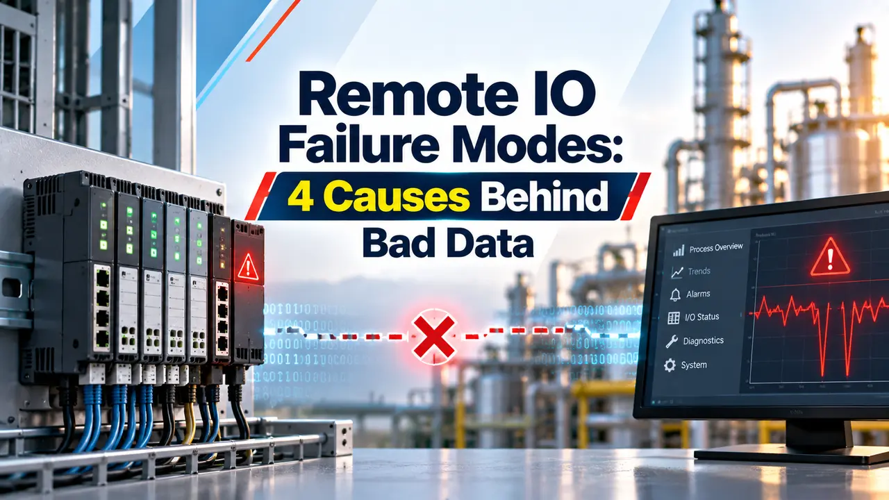
4 Categories Behind Remote IO Failure Modes
What Actually Breaks the Communication Link
A remote IO rack exchanges all of its data over a network protocol such as EtherNet IP, PROFINET, or Modbus TCP, which means the physical and logical health of that single link determines everything.
Once that link drops, the controller sees a timeout and typically either inhibits the module or holds its data at the last known value, depending entirely on how the program was configured to react.
Watchdog Timers That Catch the Failure
| Watchdog Type | Typical Timeout Range |
|---|---|
| PLC Scan Watchdog | About 10 to 200 milliseconds, often defaulting near 500 milliseconds |
| Process Watchdog | About 35 to 45 seconds, sized well above the normal process duration |
| Communication Watchdog | About 2 to 10 seconds, sized to several times the expected update interval |
A communication watchdog rarely trips on a single missed message, since most designs wait for two or three consecutive misses before declaring the link down, and several consecutive good messages before trusting it again.
Power Supply Weakness at the Remote Station
A central controller almost always ships with dual, redundant power supplies as standard practice, yet the remote IO station sitting out in the field frequently runs on just one.
Voltage dips under load, thermal aging of internal components, and a slowly degrading plant ground reference can all push that single supply toward failure long before it stops working outright.
When it finally does fail, the remote station simply goes dark, and every one of its Remote IO Failure Modes becomes irrelevant next to the fact that the entire rack has lost power completely.
Redundancy Levels Worth Understanding
A redundant communication network, wired in a ring or run in parallel over two separate paths, removes the single link weakness entirely rather than just reacting faster once it fails.
Environmental Stress Nobody Notices Until It Fails
Remote IO is almost always installed exactly where regular human attention is limited, out in a field junction box or a remote skid rather than an air conditioned control room.
Heat and poor ventilation accelerate the drift of electronic components, gradually shifting a channel's calibration long before it outright fails.
Vibration from nearby rotating equipment loosens terminals slowly, increasing terminal resistance in a way that shows up as an intermittent fault rather than a clean failure.
Condensation forming overnight or early in the morning can create inputs that flicker only at certain hours, a symptom that is easy to dismiss until the pattern is actually tracked over several days.
Why Ignoring Diagnostic Bits Is Genuinely Dangerous
Nearly every remote adapter exposes connection status bits, module health flags, and channel level fault indicators, yet many PLC programs read them only for a screen display and never wire them into actual control logic.
That gap turns a remote system into something close to useless from a safety standpoint, since the program has no way to tell the difference between a genuinely quiet process and one whose I/O has quietly stopped updating.
Predetermined Safe State
Forces a loop to a known safe condition on communication loss, guaranteeing the process cannot silently coast on bad data.
Hold Last Value
Keeps the display looking normal during a brief interruption, but can mask a genuine process excursion happening behind that frozen reading.
What Happens Downstream of a Remote IO Failure
A control loop that suddenly loses its process variable does not simply pause and wait politely, it either freezes its output at the last command or, worse, keeps acting on a value that stopped updating an hour ago.
For an ordinary process loop that mostly means a bump in quality or a wasted batch, an annoyance that shows up on a shift report rather than an incident report.
For a safety instrumented function tied to that same remote rack, the stakes are entirely different, since a frozen normal reading during an actual overflow or overpressure event can delay the very shutdown the system exists to trigger.
This is exactly why IEC 61511 style safety design insists on a defined fail safe state for safety I/O rather than leaving the behavior on communication loss to whatever the default configuration happens to be.
Beyond the single incident, repeated small failures chip away at overall uptime too, since every nuisance trip from a marginal cable or a borderline power supply eventually adds up to real lost production time across a year.
Installation Habits That Prevent Most of This
None of these habits are exotic or expensive, which is exactly the point, since most Remote IO Failure Modes trace back to a small maintenance or configuration gap rather than a genuinely defective piece of hardware.
A short commissioning checklist that forces a technician to physically confirm cable routing, terminal torque, and ambient temperature before a rack goes into service catches a surprising share of problems that would otherwise surface months later as an intermittent nuisance.
Building a Monitoring Habit Around These Failures
Trending connection status and health bits over weeks, not just watching them live on a screen, is what actually reveals a slow degrading pattern before it becomes an outright failure.
A cable that drops out once a month for a few seconds rarely triggers an alarm on its own, yet that same pattern charted over a quarter tells a very different and far more useful story.
Pairing that historical trend with simple environmental logging, cabinet temperature and humidity in particular, often points straight at the root cause behind a set of Remote IO Failure Modes that otherwise look completely unrelated to each other.
Building that habit costs very little compared to the alternative, which is discovering the pattern only after a nuisance trip finally escalates into something that actually costs the plant real production time.
Watch: What Is Remote IO
Remote IO Failure Modes Questions Engineers Ask
Related Articles on This Site
- PLC Redundancy, Hot Standby
- Redundant Power Supply PLC
- PLC Watchdog Timer Explained
- DCS Controller Redundancy Types
- Network Switches in SCADA and DCS
External References
- Understanding Remote I O in PLC Control Systems
- Communication and Power Redundancy for Control Devices
What We Learn Today
- Remote IO Failure Modes group into communication loss, power weakness, environmental stress, and ignored diagnostics.
- A predetermined safe state protects a safety loop far better than simply holding the last known value during an interruption.
- Diagnostic bits already exist on most remote adapters, so the real fix is often wiring them into logic that actually reacts.