
A residual current device only protects people when it can actually see the kind of leakage current that flows. Modern loads such as drives, inverters and EV chargers produce DC and high frequency leakage that older devices simply cannot detect.
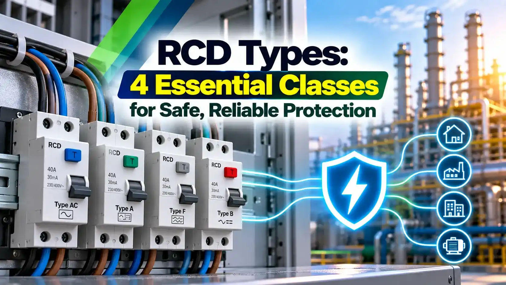
Choosing between RCD types AC, A, F and B decides whether a shock or fault current is actually detected. This guide explains each class in plain language with practical selection and testing advice.
What Is a Residual Current Device and Why RCD Types Matter?
A residual current device compares the current flowing out on the line conductors with the current returning on the neutral, and it trips when the difference exceeds its rated residual current. The RCD types defined in IEC 60755 and IEC 62423 describe which shapes of that difference current the device can reliably detect.
In a healthy circuit the currents cancel inside a toroidal core, so the secondary winding sees nothing. When current leaks to earth through insulation damage or a human body, the imbalance magnetises the core and the trip relay opens the contacts, which is the basic idea behind the older ELCB and RCCB devices as well.

The problem is that modern electronics do not always leak a clean 50 Hz sine wave. A rectifier can leak pulsating or smooth DC, and a drive can leak a mix of frequencies, so knowing the RCD types is as important as knowing the current rating when you study electrical shock causes and prevention.
The 4 RCD Types at a Glance
Detects sinusoidal AC residual current only. Suited to purely resistive and simple loads such as heaters and lamps.
Detects sinusoidal AC plus pulsating DC, and tolerates up to 6 mA of smooth DC without losing sensitivity.
Adds mixed frequency detection for single phase inverter loads, with extra surge immunity and 10 mA smooth DC tolerance.
Detects everything above plus smooth DC and AC up to 1 kHz, as required for 3 phase rectifiers.
The Electrical Installation Guide explains that the classes nest inside one another. Type B meets the requirements of F, A and AC, so moving up the ladder never loses protection.
A Type AC device can be blinded by as little as a few milliamps of smooth DC, because the DC saturates its magnetic core. Once the core is saturated, even a dangerous AC fault current may fail to trip it.
Residual Waveforms Each Class Detects
| Residual waveform | Type AC | Type A | Type F | Type B |
|---|---|---|---|---|
| Sinusoidal AC at 50 Hz | Yes | Yes | Yes | Yes |
| Pulsating DC (half wave) | No | Yes | Yes | Yes |
| Mixed frequency composite | No | No | Yes | Yes |
| Smooth DC (3 phase rectifier) | No | No | No | Yes |
| AC up to 1 kHz | No | No | No | Yes |
For all RCD types, sinusoidal AC leakage comes from insulation faults or a person touching a live part. Pulsating DC appears when a single phase diode or thyristor circuit leaks, which is common in lighting dimmers, small chargers and switch mode power supplies.
Mixed frequency leakage is produced by single phase inverters, where the motor frequency, the switching frequency and 50 Hz combine in one waveform. Smooth DC is produced when a 3 phase bridge rectifier, like the front end explained in VFD working principle, leaks through a fault on its DC bus or output.
Type B+ is a variant from the German standard DIN VDE 0664 400. It extends detection to 20 kHz with a trip limit of 420 mA, which improves fire protection with high frequency drives.
Sensitivity Ratings and Time Delayed Devices
All RCD types are offered in several sensitivities, and a 30 mA device is used for additional protection against direct contact, because ventricular fibrillation risk rises sharply above this level. Ratings of 100 mA and 300 mA are used for fire protection, since an earth fault current of a few hundred milliamps through carbonised insulation can start a fire.
Time delayed S type devices, available in the main RCD types, carry a deliberate delay so that a downstream 30 mA device clears the fault first. ABB lists selective devices with break times of roughly 0.13 to 0.5 s, which is how discrimination is achieved between an incomer and final circuits.
Never place two instantaneous devices of the same rating in series and expect selectivity. Use an S type device of at least three times the downstream rating on the incomer.
Trip Time Limits and Testing Rules
At 1 × IΔn : 300 ms
At 2 × IΔn : 150 ms
At 5 × IΔn : 40 ms
Time delayed S type
At 1 × IΔn : 130 ms minimum, 500 ms maximum
At 5 × IΔn : 50 ms minimum, 150 ms maximum
ABB states that an instantaneous device must break within 0.3 s at its rated residual current and within 0.04 s at high fault currents. These limits are checked with an RCD tester during initial verification, together with the earth fault loop impedance Zs test.
How to Test RCD Types on Site in 6 Steps
Different RCD types need different test waveforms, so always set the tester to match the device. Testing a Type B unit only with a sine wave does not prove its smooth DC function, so use a tester that supports DC ramp injection.
If the trip time is close to the 300 ms limit, check the terminations and the test lead contact before blaming the device. A loose neutral can distort the reading.
Selecting RCD Types for EV Chargers, VFDs and Solar
Doepke explains that the 2026 amendment of BS 7671 requires that DC residual current above 6 mA must not impair the operation of the device protecting an EV charger. A standard Type A device therefore needs a supplementary 6 mA DC detection device, while a Type B device covers the full range on its own.
Drives create high frequency leakage through cable capacitance and EMC filters, as described in power quality issues with VFD and PLC systems. Among RCD types, choose one with a suitable frequency response and keep motor cables short to limit the normal leakage current.
A solar inverter without galvanic isolation can push smooth DC into an earth fault. This is why many inverter manuals state which of the RCD types is permitted on the AC side.
RCCB vs RCBO: Which Device Carries the Protection?
- Detects earth leakage but has no overcurrent trip.
- Protects a group of circuits at lower cost.
- Needs a separate MCB or fuse upstream or downstream.
- Combines residual and overcurrent protection in one unit.
- One fault trips only one circuit, so less disruption.
- Costs more per circuit and takes more panel space.
An RCCB, offered in most RCD types, relies on a separate breaker for overload and short circuit protection, and that breaker must be sized as shown in how to calculate MCB rating. An RCBO gives each final circuit its own device, which is preferred for critical loads and EV points.
Touch Voltage and Earth Resistance Check
In a TT system the fault current returns through the soil, so the resistance of the installation earth electrode decides the touch voltage. The TN, TT and IT earthing systems article explains why an RCD is almost always required in TT installations.
RA max = 50 ÷ IΔn
Example 1, 30 mA device:
RA max = 50 ÷ 0.03 = 1666.67 Ω
Measured RA = 200 Ω, so the condition is met
Example 2, 300 mA S type incomer:
RA max = 50 ÷ 0.3 = 166.67 Ω
RA is the sum of the earth electrode resistance and the protective conductor resistance to the exposed parts. Measure it and see earthing resistance calculation for rod and grid formulas.
Maximum Earth Resistance Calculator
Use 25 V as the limit for wet and agricultural locations, where body resistance is lower. The calculator applies to all RCD types, since the rule depends only on the rated residual current.
Common Myths About RCD Types
Installation Checklist and Common Mistakes
- Confirm the load type and choose among RCD types by its leakage waveform.
- Check that the neutral passes through the device and is not shared with other circuits.
- Use an S type device upstream when a 30 mA device is fitted downstream.
- Verify the earth resistance and record it against the calculated maximum.
- Record trip times at 1 × IΔn and 5 × IΔn in the handover file.
Workers who test RCD types on live circuits must follow the approach limits and PPE rules given in NFPA 70E electrical safety. For substation work, touch and step limits from IEEE 80 step and touch voltage apply instead.
The national wiring rules in India and abroad increasingly call for Type A as the minimum, and a good summary of these codes is in electrical regulations and standards. Always check the local rules before selecting the final device.
ABB Technical Guide on RCD Types (PDF)
Video: RCD Types Explained With Tests
RCD Types FAQ
The four main RCD types are AC, A, F and B, defined in IEC 60755 and IEC 62423. They differ mainly in the residual current waveforms they can detect reliably.
Type AC sees only sinusoidal AC, while Type A adds pulsating DC from single phase rectifiers. Type F adds mixed frequency leakage, and Type B adds smooth DC and frequencies up to 1 kHz.
Most homes and plants now contain electronic loads with rectifiers, such as chargers, LED drivers and inverters. These loads can leak DC current that a Type AC device cannot detect at all.
Smooth DC can also saturate the magnetic core of a Type AC device and reduce its sensitivity. A saturated core may then fail to trip even on a dangerous AC fault through a person.
An EV charger needs Type B protection, or Type A combined with a 6 mA DC detection device. The DC detection function is often built into the charger itself by the maker.
Doepke notes that BS 7671 now requires that DC leakage above 6 mA must not impair the device. Where several chargers with DC detection share one circuit, an upstream Type B device is required.
S type means a selective or time delayed device used higher up in the distribution system. It waits a short time before tripping so that downstream 30 mA devices clear the fault first.
ABB gives break times of about 0.13 to 0.5 s for these devices at rated current. They are used as incomers, usually with 100 mA or 300 mA ratings for fire protection.
A general device must trip within 300 ms at its rated residual current and within 150 ms at twice that value. At five times the rated current it must trip within 40 ms.
These limits come from IEC 61008 and IEC 61009 for RCCB and RCBO units. Always record both the 1 × IΔn and 5 × IΔn times during initial verification and periodic inspection.
Most makers recommend pressing the test button every three to six months, and the interval is often printed on the front. This keeps the mechanism free and proves it can still trip.
The button does not measure trip time, so it is not a full test of the protection. A proper instrument test should be done during every periodic inspection of the installation.
An RCCB detects only earth leakage current and has no overload or short circuit protection of its own. It must therefore be combined with an MCB or fuse for overcurrent protection.
An RCBO combines residual and overcurrent protection in one compact unit for each circuit. It costs more per way, but it limits any fault to a single circuit and reduces disruption.
Related Articles
- MCB vs MCCB vs ELCB vs RCCB
- TN, TT and IT Earthing Systems
- Earth Fault Loop Impedance Zs Testing
- Electrical Shock Causes, Effects and Prevention
- Earthing Resistance Calculation
External References
- Protection Against Earth Faults with Residual Current Devices, ABB
- Electric Vehicle Charging and the Role of Residual Current Devices, Doepke
- Residual Current Device, Wikipedia
What We Learn Today
- RCD types AC, A, F and B differ in the leakage waveforms they detect, from plain sinusoidal AC up to smooth DC and 1 kHz.
- EV chargers need Type B, or Type A with 6 mA DC detection, while 3 phase drives and many solar inverters also need Type B protection.
- In a TT system the earth resistance must satisfy RA × IΔn ≤ 50 V, and trip times must stay under 300 ms at the rated current.