
A thermocouple transmitter has several parameters that are specific to thermocouple sensors and are not present when the same transmitter is configured for an RTD input.
Getting these parameters right
sensor type code, cold junction compensation mode, and burnout direction is the difference between a reliable loop and one that fails silently.
A thermocouple transmitter with the wrong TC type produces errors of 10 to 50 degrees C across the range.
No output trimming can fix this. The sensor type must match the physical thermocouple.
We will cover the thermocouple-specific parameters you need to configure: sensor type selection, cold junction compensation, burnout direction, LRV and URV entry, and the HART secondary variable assignment for thermocouple loops.
We will also include a step-by-step configuration sequence, worked examples, common mistakes, and a comparison table of thermocouple type codes and their temperature ranges.
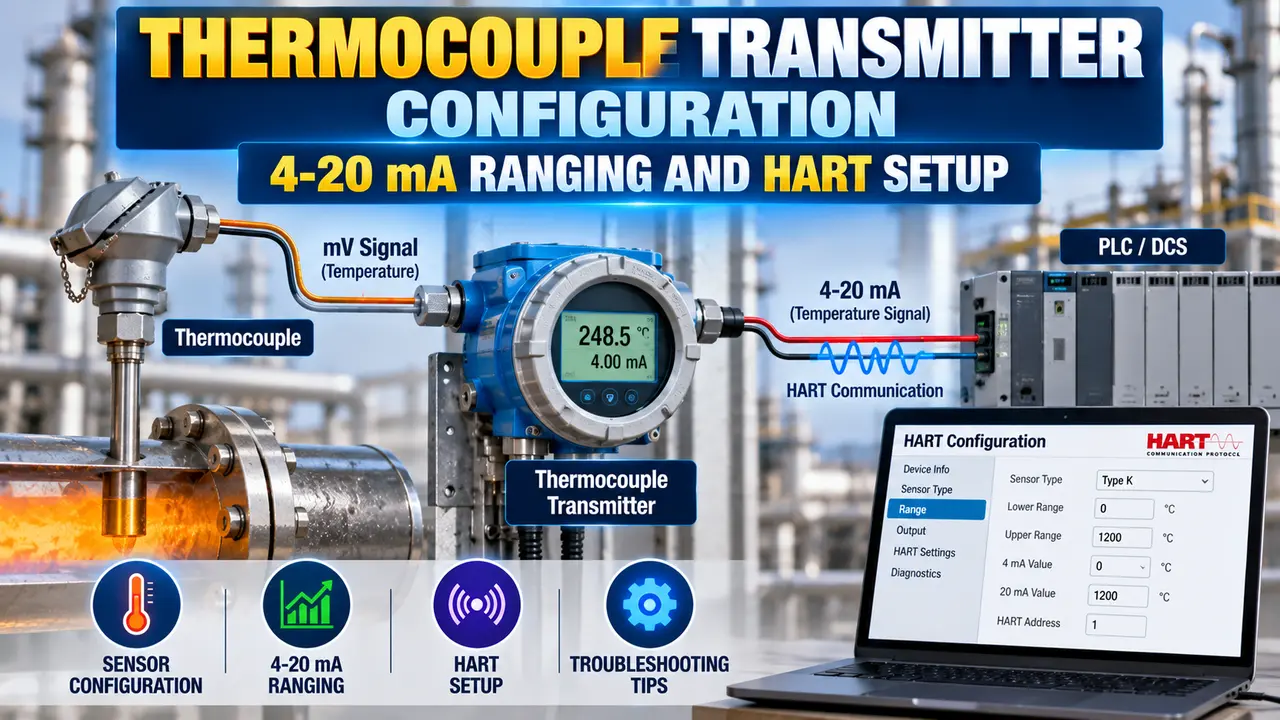
Why Thermocouple Transmitter Configuration Differs from RTD
A thermocouple generates a small millivolt signal from the temperature difference between the measuring junction and the reference junction at the transmitter terminals.
The reference junction at the terminals is called the cold junction.
An RTD transmitter measures resistance. A thermocouple transmitter must also linearise the millivolt input against the TC characteristic curve and add cold junction compensation for the terminal temperature.
These three differences create several transmitter parameters that are unique to thermocouple configuration and do not appear in RTD setup menus.
Thermocouple Type Selection: Codes and Temperature Ranges
The first and most critical configuration parameter is the thermocouple type. Each type code uses a different characteristic curve to convert millivolt input into a temperature value.
If the wrong type is selected, the transmitter linearises against the wrong curve. The error is non-linear and changes across the range. The only fix is to configure the correct TC type.
| TC Type | Metal Pair | Typical Range | Common Applications |
|---|---|---|---|
| Type K | Nickel-Chromium / Nickel-Aluminium | minus 200 to 1260 degrees C | Most common general-purpose TC. Used widely in process plants, kilns, and heat treatment. |
| Type J | Iron / Copper-Nickel | minus 40 to 750 degrees C | Older installations, lower-temperature oxidising and reducing atmospheres. Being phased out in new designs. |
| Type T | Copper / Copper-Nickel | minus 200 to 350 degrees C | Cryogenic service, food and pharma cold applications, refrigeration. |
| Type E | Nickel-Chromium / Copper-Nickel | minus 200 to 900 degrees C | Highest EMF output per degree of all common types. Used where sensitivity is important. |
| Type N | Nickel-Chromium-Silicon / Nickel-Silicon | minus 200 to 1300 degrees C | High-temperature service with improved drift stability compared to Type K. |
| Type S | Platinum-10% Rhodium / Platinum | 0 to 1450 degrees C | High-accuracy high-temperature service: steel, glass, ceramics. Used as a calibration reference. |
| Type R | Platinum-13% Rhodium / Platinum | 0 to 1450 degrees C | Same applications as Type S. Slightly higher EMF output. Used in high-temperature furnaces. |
| Type B | Platinum-30% Rhodium / Platinum-6% Rhodium | 600 to 1700 degrees C | Very high temperature service only. Output is extremely low below 600 degrees C. Do not use below this range. |
Cold Junction Compensation: Modes and Error Sources
A thermocouple measures the temperature difference between its measuring junction and its cold junction. The cold junction is where the thermocouple wires terminate at the transmitter input terminals.
The transmitter must know the temperature at its own terminals to calculate the absolute process temperature. This measurement and correction is called cold junction compensation (CJC).
CJC Modes Available in Most Transmitters
Burnout Direction: Upscale vs Downscale
A thermocouple generates no voltage when the wire breaks. The transmitter detects this open-circuit and drives its output to a predefined level. This is called the burnout or sensor failure response.
The burnout direction determines whether the transmitter drives its output to a high value or a low value when a wire break is detected.
Setting LRV and URV for a Thermocouple Loop
The Lower Range Value (LRV) is the temperature that corresponds to 4 mA output. The Upper Range Value (URV) is the temperature that corresponds to 20 mA output.
The LRV and URV must both fall within the allowable range of the selected TC type. For Type K, this is minus 200 to 1260 degrees C.
Values outside this range are rejected or produce an error.
TC type: Type K (selected to cover the full range with margin)
LRV: 150 degrees C (corresponds to 4 mA)
URV: 450 degrees C (corresponds to 20 mA)
Span: 300 degrees C
Normal operating point: 280 degrees C = 4 + (280 minus 150) divided by 300 x 16 = 10.93 mA
Burnout direction: Upscale (21 mA) because a false low reading would increase reactor heat input, which is dangerous
CJC mode: Internal (standard field installation)
Result: Normal operation sits at 44% of span. Alarm at 380 degrees C = 17.87 mA. Transmitter output goes to 21 mA if TC wire breaks.
HART Configuration: Step-by-Step for a Thermocouple Transmitter
HART communication allows the complete transmitter configuration to be read and written digitally using a HART communicator (such as the Emerson 475 or AMS Trex) connected anywhere on the 4-20 mA loop.
The minimum loop resistance for HART is 250 ohms. Most DCS input cards include a 250 ohm resistor. Verify the resistance before connecting on a live loop.
Common Thermocouple Transmitter Configuration Mistakes
Watch: Thermocouple Transmitter HART 475 Calibration and Configuration
Thermocouple Transmitter Configuration Questions
Related Articles on This Site
- Basics of Thermocouples and RTD Explained
- Thermocouple Polarity Identification Guide
- Thermocouple Grounded vs Ungrounded Junction
- HART Protocol Working Principle Explained
- Why 4-20 mA Is the Best Signal for Industrial Automation
External References
- Calibrating a HART Temperature Transmitter | Fluke
- How to Calibrate an RTD/TC HART Temperature Transmitter | Beamex
What We Learn Today
- TC type is the most critical step. A wrong TC type produces a non-linear error that cannot be corrected by trimming. CJC corrects for the terminal temperature so the output is an absolute process temperature.
- Burnout direction is set based on the process safety requirement. Upscale (21 mA) or downscale (3.6 mA) drives the output out of range on TC wire break. Always enable burnout detection on thermocouple loops.
- HART configuration covers sensor type, CJC mode, LRV, URV, burnout direction, SV assignment, damping, and device tag. Configure the SV as the terminal temperature to monitor CJC quality. Use sensor trim for temperature errors, not output trim.