
A temperature switch gives a discrete relay contact when temperature crosses a setpoint. A temperature transmitter gives a continuous 4-20 mA output proportional to measured temperature.
These are fundamentally different instruments. Understanding the difference prevents the most common temperature instrumentation specification errors.
This guide explains when to use a temperature switch, when to use a temperature transmitter, and how to decide between them.
The temperature switch answers: "has the temperature crossed this setpoint?" The temperature transmitter answers: "what is the current temperature?"
Both are valid tools. The mistake is using a transmitter with a DCS alarm to do a job a direct-wired switch would do more reliably and at lower cost.
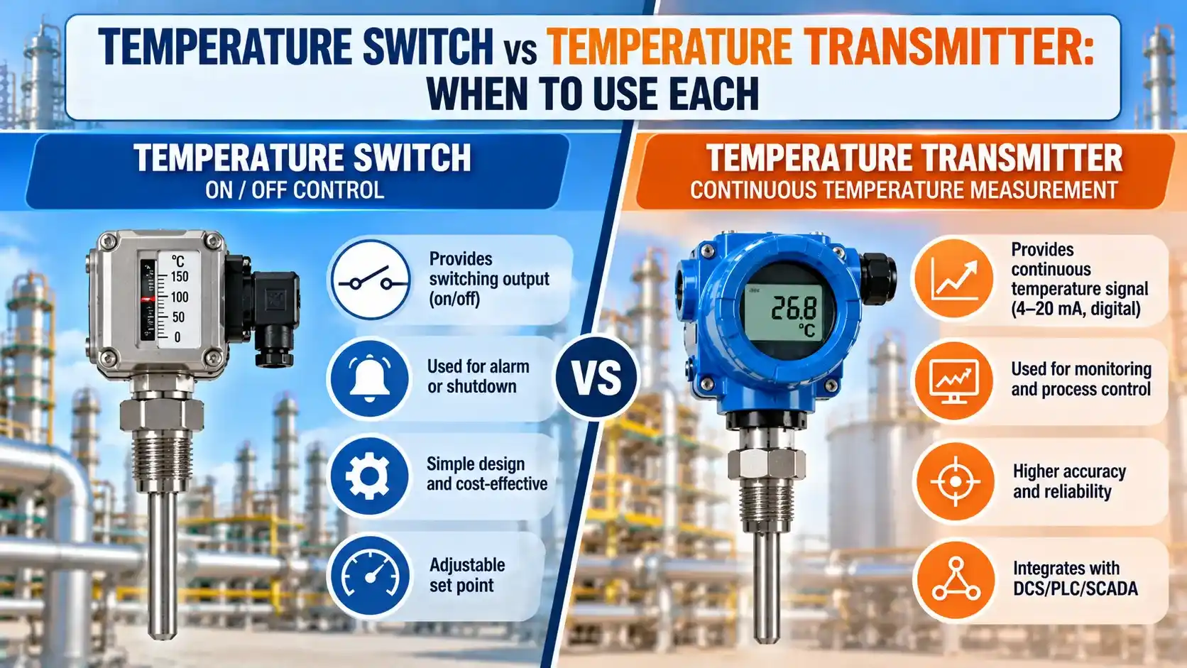
temperature switch vs transmitter: the core Difference
A this instrument is a binary device. It has two states: normal (contact open or closed at normal temperature) and tripped (contact changed when temperature crosses the setpoint). Nothing in between.
A temperature transmitter is an analogue device. It outputs a continuous signal representing every value between its lower and upper range.
The DCS reads this signal continuously and can display, control, alarm, record, or use it in a calculation.
Two metals with different thermal expansion coefficients are bonded together. As temperature rises, the faster-expanding metal bends the strip, eventually snapping it to a new position and opening or closing the circuit.
Modern electronic temperature switches use a thermocouple or RTD as the sensing element and electronic trip circuitry, but many field-mounted mechanical temperature switches still use bimetallic disc or vapour-actuated capsule elements today — because they require no external power and are inherently fail-safe.
temperature switch explained and When to Use It
How a Temperature Switch Works
A mechanical temperature switch (also called a thermostat in HVAC) uses a bimetallic disc, a vapour-pressure capsule, or a rod-and-tube element to actuate a microswitch at the setpoint.
An electronic temperature switch uses a thermocouple or RTD as the sensing element, feeding an electronic comparator circuit that trips a relay output when the measured temperature crosses the programmed setpoint.
Both types produce a SPDT relay output (one NO, one NC terminal).
The contact changes state when temperature crosses the trip point, with a deadband between trip and reset. See the deadband guide for how this applies to both pressure and temperature switches.
When to Use a Temperature Switch
Equipment protection: A temperature switch directly and simply protects equipment from overtemperature or undertemperature.
Examples: high-temperature cutout on a motor winding, overtemperature trip on a heat exchanger, freeze protection on a pipeline.
No DCS required: A switch wires directly to a motor starter, solenoid valve, or alarm panel.
No DCS, no signal conversion, no power supply loop — just a contact at the setpoint. This simplicity makes it more reliable than a transmitter-based alarm for standalone protection.
Safety functions (SIS): An electronic switch with a direct relay output is often preferred over a transmitter for SIL-rated trips.
The signal chain has fewer components — no DCS loop, no A/D conversion, no software alarm to mis-configure — reducing the probability of dangerous failure.
A switch with too small a deadband will chatter: it trips at 80°C and resets immediately at 79°C, cycling rapidly in processes with minor temperature fluctuations around the setpoint.
For motor overtemperature protection, a deadband of 5 to 10°C is typical. For process high-temperature alarms, 3 to 5°C is common. Always set the deadband wider than the normal temperature fluctuation at the trip point. See also the deadband guide for the equivalent concept in pressure switches.
As the bulb temperature rises, the liquid vapourises, generating vapour pressure inside the sealed system. This pressure deflects a diaphragm, which actuates the switch. The vapour pressure is determined solely by the liquid-vapour equilibrium of the fill fluid — making the setpoint inherently stable and unaffected by changes in ambient temperature along the capillary tube.
This self-contained, zero-power design makes vapour-pressure temperature switches very reliable for process overtemperature protection in locations without instrument air or electrical supply.
temperature transmitter explained and When to Use It
How a Temperature Transmitter Works
A temperature transmitter converts the output of a thermocouple or RTD into a standardised 4-20 mA or digital HART/Fieldbus signal.
The output is continuous and proportional to the measured temperature across the configured range.
The transmitter provides cold junction compensation, sensor linearisation, burnout detection, and HART communication. See the temperature transmitter guide for details.
When to Use a Temperature Transmitter
Process control: A temperature transmitter is essential for continuous PID control feedback.
A temperature switch cannot provide a continuous PV signal — it only tells you whether temperature is above or below one setpoint.
Temperature trending: A temperature transmitter feeds a continuous value to the DCS historian for trending and process upset investigation.
a switch provides none of this data — it records only the time of the trip, not the temperature history.
Multiple setpoints: A single transmitter connected to the DCS generates as many alarm setpoints as needed by DCS programming.
A temperature switch provides one trip point per switch body, though dual-setpoint models exist.
High accuracy: Below ±1°C accuracy (pharmaceutical, food, chemical reactor) requires a calibrated Pt100 transmitter achieving ±0.1 to ±0.3°C.
A mechanical temperature switch cannot approach this accuracy.
If a thermocouple wire breaks and burnout detection is disabled, the transmitter may output a frozen value or a mid-range value that looks like a valid temperature reading to the DCS. The process control loop continues running, but the feedback it is using is meaningless.
With burnout detection enabled, the transmitter drives its output to 3.6 mA (downscale burnout) or 21 mA (upscale burnout) on sensor failure — a clearly out-of-range value that the DCS alarm system can detect. See the temperature transmitter burnout guide for the wiring details.
This lets a maintenance engineer read both the raw resistance and the temperature simultaneously from a single connection point — without disconnecting any wires or breaking the loop.
The raw resistance value is the diagnostic tool: comparing it against the Pt100 resistance-temperature table confirms whether the RTD is reading correctly or has drifted due to moisture ingress, lead wire corrosion, or mechanical damage. See the thermocouple and RTD guide for the Pt100 resistance-temperature relationship.
temperature switch vs transmitter: full Comparison
| Parameter | Temperature Switch | Temperature Transmitter |
|---|---|---|
| Output type | Discrete relay contact (SPDT): one output state per trip | Continuous analogue 4-20 mA or digital (HART, Fieldbus, Profibus) |
| Primary function | On/off protection and alarm: "has the temperature crossed this point?" | Continuous measurement and control: "what is the temperature right now?" |
| Number of setpoints | One (or two for dual-setpoint models) | Unlimited (all alarm setpoints are programmed in the DCS) |
| Accuracy | ±1 to ±5°C (mechanical bimetallic); ±0.5 to ±1°C (electronic with RTD/TC) | ±0.1 to ±0.5°C (Pt100 RTD transmitter after calibration) |
| Response time | Mechanical: 2 to 10 seconds. Electronic: same as RTD/TC sensor time constant. | Same as RTD/TC sensor time constant, plus transmitter update rate (typically 100 to 500 ms) |
| Process control | Cannot provide continuous PV for a PID control loop | The standard instrument for temperature control loops |
| DCS connection required | No: direct hard-wired to motor starter, solenoid, or alarm panel | Yes: requires a 4-20 mA analogue input card or HART interface in the DCS or SIS |
| Power supply | Mechanical: none. Electronic: 24 VDC loop power or separate supply. | 24 VDC loop-powered (2-wire) or externally powered (4-wire) |
| Temperature trending | No: records only the time of the trip, not the temperature history | Yes: continuous value fed to DCS historian for trending and analysis |
| SIL suitability | Good for SIL-rated initiating elements: direct relay output, fewer components in signal chain | Suitable as SIS initiating element when transmitter is SIL-certified and loop is correctly designed |
| Cost | Lower: mechanical types from a few hundred rupees; electronic from ₹3,000 to ₹15,000 | Higher: head-mounted transmitter from ₹8,000 to ₹40,000 plus DCS input card |
| Best for | Equipment overtemperature protection, motor winding protection, freeze protection, simple safety trips | Process control loops, trending, multi-alarm DCS applications, high-accuracy pharmaceutical and food applications |
instrument selector
Watch: Temperature Transmitters — Tasks, Traits and Technology
FAQ: switch vs transmitter questions
External References
- Temperature Transmitters: Selection, Types and Application | Endress+Hauser (2025)
- Temperature Switch Types and Selection | WIKA (2025)
What We Learn Today
- A temperature switch gives a discrete relay contact output at one setpoint. A temperature transmitter gives a continuous 4-20 mA signal proportional to temperature. They answer different questions and are used for different purposes.
- Use a temperature switch for equipment protection (motor overtemperature, freeze protection, overtemperature cutout) — no DCS required, direct-wired to the load. Use a transmitter for process control loops, trending, and multi-alarm DCS applications.
- Both can coexist on the same thermowell: the switch provides direct overtemperature protection, and the transmitter provides the continuous PV for the control loop and DCS display.