Level Transmitter 5 Point Calibration: As-Found and As-Left Procedure

Share:
Level Measurement
Level Transmitter 5-Point Calibration: As-Found and As-Left Procedure

Level transmitter calibration verifies and corrects the relationship between process level and 4-20 mA output across the full range.

A 5-point calibration checks accuracy at 0%, 25%, 50%, 75%, and 100% of span to confirm linearity, not just the endpoints.

This guide covers the complete level transmitter calibration procedure including as-found documentation, adjustment, as-left verification, and the 5-point calibration table format used in industrial plant records.

0% 25% 50% 75% 100% As-Found and As-Left mA to Level Conversion Acceptable Error Limits

Level transmitter calibration at five points confirms accuracy across the full range. A transmitter with a non-linear error at 50% passes a 2-point check but gives wrong readings in service.
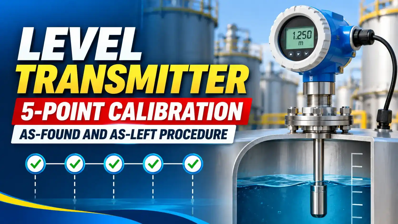
Level Transmitter

Level Transmitter Calibration: Why 5 Points Matter

Hello! Today we are going through the complete 5-point level transmitter calibration procedure: as-found reading, adjustment, and as-left verification. This is the standard calibration format used in process plants, refineries, and water treatment facilities. Whether you are calibrating a DP transmitter, a guided wave radar, or an ultrasonic level transmitter, the 5-point as-found and as-left format applies to all of them.

A level transmitter outputs 4 mA at 0% of span and 20 mA at 100%. A correct reading at both endpoints does not guarantee linearity at midrange.

A 5-point calibration catches linearity errors by checking at five equally spaced inputs: 0%, 25%, 50%, 75%, and 100%.

Three terms must be understood before starting: as-found, as-left, and acceptable error limit. Click any term to expand.

As-Found: The reading recorded before any adjustment is made. As-found data is the legal and audit record of how the instrument was performing in service before the technician touched it. If an instrument is found outside its acceptable error limit, the as-found reading is used to assess whether any process measurements taken since the last calibration were compromised. Never adjust the instrument before recording all as-found readings.
As-Left: The reading recorded after adjustment and verification. This confirms the instrument was left in a correct, calibrated state before the technician walked away. The as-left values must fall within the acceptable error limit at all five calibration points. Both as-found and as-left values are documented in the calibration record.
Acceptable Error Limit: The maximum allowable deviation between the applied input and the measured output, expressed as a percentage of span or in engineering units. Typical industrial acceptance criteria for a level transmitter is within plus or minus 0.5% of span (equivalent to plus or minus 0.08 mA on a 16 mA span). Safety instrumented system (SIS) level transmitters may have tighter limits specified in the safety requirements specification.
5 points
0%, 25%, 50%, 75%, 100% of span checked in both directions (upscale and downscale)
±0.5%
Typical acceptable error limit for process level transmitter calibration
4 mA
Expected output at 0% of span (LRV). Transmitter output at empty or minimum level.
20 mA
Expected output at 100% of span (URV). Transmitter output at full or maximum level.
Advertisement

Before You Start: Equipment and Preparation

Level transmitter calibration requires a calibration source to simulate the measured variable, a reference standard to measure the output, and the calibration record form. The specific calibration source depends on the transmitter technology.

Transmitter TypeCalibration Source (Input)Output Measurement
DP transmitter (differential pressure level)Precision hand pump or dead-weight tester applying known differential pressure equal to the level spanCalibrated digital multimeter or loop calibrator measuring mA
Guided wave radar (GWR)Physical level reference in the vessel or calibration chamber, or manufacturer configuration software with empty and full reference pointsHART communicator reading PV or mA at the transmitter
Ultrasonic level transmitterKnown physical distance from the sensor face to the process surface (use a tape measure and reference reflector)Calibrated mA meter or HART communicator
Capacitance level transmitterCalibration cup filled to known levels, or manufacturer wet calibration procedure using the actual process fluidCalibrated mA meter
Float or displacerKnown weights applied to simulate buoyancy forces at defined level points (dry calibration) or physical fill to defined levels (wet calibration)Calibrated mA meter
For DP level transmitters, the differential pressure applied at each calibration point corresponds to the hydrostatic head of the process fluid at that level. The pressure at 100% level = fluid density × gravity × vessel height. See the DP transmitter level measurement guide for the open tank and closed tank calculations used to determine the LRV and URV pressure values.
Advertisement

5-Point Level Transmitter Calibration Procedure

1
Retrieve the calibration record and instrument data sheet. Confirm the transmitter tag number, calibrated range (LRV to URV in engineering units), acceptable error limit, and last calibration date. Check the instrument data sheet for the DP span, fluid density, and installation type (open tank, closed tank, wet leg, dry leg) before applying any pressure input.
2
Isolate and vent the transmitter safely. Follow the site permit to work and isolation procedure. For a DP level transmitter, close the equalising valve, then close the high and low side root valves. Vent to atmosphere through the vent screws. Confirm zero differential pressure at the transmitter before connecting the calibration source. See the zero and span adjustments guide for how zero shift can occur after isolation.
3
Connect the calibration source and reference standard. Connect the pressure source (for DP type) or configure the physical reference (for radar or ultrasonic). Connect a calibrated mA meter or loop calibrator in series with the loop. Power the transmitter via the loop calibrator or existing loop supply. See the 4-20 mA signal guide for loop wiring.
4
Record as-found readings at all five points (do not adjust yet). Apply each of the five input values corresponding to 0%, 25%, 50%, 75%, and 100% of the calibrated span. At each point, allow the reading to stabilise, then record the actual mA output. Also apply inputs upscale (0% to 100%) and then downscale (100% to 0%) to check for hysteresis. Enter all values in the as-found column of the calibration record.
5
Assess the as-found results against the acceptable error limit. Calculate the error at each point: Error% = (Actual output mA minus Expected output mA) / 16 mA × 100. If all five points are within the acceptable error limit, the transmitter passes as-found. If any point exceeds the limit, document this as an out-of-tolerance finding before proceeding with adjustment.
6
Adjust the transmitter if required. For a HART smart transmitter, use the HART communicator to perform sensor trim (corrects the input side) or output trim (corrects the DAC output). For a conventional transmitter, adjust the zero potentiometer at 0% span and the span potentiometer at 100% span. See the sensor trim and output trim guide for the step-by-step trim procedure. After adjustment, always re-verify all five points before recording as-left values.
7
Record as-left readings at all five points. Repeat the five-point check after adjustment. Record all readings in the as-left column. All five points must be within the acceptable error limit before the transmitter is returned to service. Sign and date the calibration record. Restore all isolation valves to normal operating position and confirm the transmitter reading matches the DCS indicated value.

Expected mA at Each Calibration Point

Expected mA at any calibration point
Expected mA = 4 + (% span / 100) × 16
0% span: 4 + (0/100) × 16 = 4.00 mA
25% span: 4 + (25/100) × 16 = 8.00 mA
50% span: 4 + (50/100) × 16 = 12.00 mA
75% span: 4 + (75/100) × 16 = 16.00 mA
100% span: 4 + (100/100) × 16 = 20.00 mA

Error% = (Actual mA minus Expected mA) / 16 × 100
Acceptable: Error% within plus or minus 0.5% of span (equals plus or minus 0.08 mA)

5-Point Calibration Table Format

% SpanApplied InputExpected mAAs-Found mAAs-Found Error%As-Left mAAs-Left Error%Pass/Fail
0%LRV (e.g. 0 mmH2O)4.00Record hereCalculateRecord hereCalculateP/F
25%25% of span8.00Record hereCalculateRecord hereCalculateP/F
50%50% of span (midpoint)12.00Record hereCalculateRecord hereCalculateP/F
75%75% of span16.00Record hereCalculateRecord hereCalculateP/F
100%URV (e.g. 1000 mmH2O)20.00Record hereCalculateRecord hereCalculateP/F
If the transmitter fails the as-found check (any point outside the acceptable error limit), raise a non-conformance report before making any adjustment. The as-found out-of-tolerance result must be investigated: determine when the drift occurred and whether any process measurement or control action since the last calibration was affected. Do not simply adjust and close the record without investigation. See the correction factor guide for how calibration adjustments are documented.

Level Transmitter Calibration Calculator

5-Point Calibration Error Calculator
Enter as-found or as-left mA readings to calculate error at each calibration point
-
-

Watch: Level Transmitter Calibration Procedure

Advertisement

Level Transmitter Calibration Questions

Why do a 5-point calibration instead of just zero and span?
A 2-point check only confirms 0% and 100%. A transmitter can pass a 2-point check with a significant linearity error at midrange. The 5-point calibration verifies the output is correct across the full range.
What is the difference between as-found and as-left readings?
As-found: the reading before any adjustment, documenting in-service performance. As-left: the reading after adjustment, confirming the instrument was returned within tolerance. Both go in the calibration record.
What is the acceptable error limit for level transmitter calibration?
Typically plus or minus 0.5% of span (plus or minus 0.08 mA). SIS level transmitters may have tighter limits in the safety requirements specification, often plus or minus 0.25% or better.
What is the expected mA at 50% of span?
12.00 mA. Formula: 4 + (50/100) × 16 = 12.00 mA. For a plus or minus 0.5% limit, any reading outside 11.92 to 12.08 mA fails at this point.
Can level transmitter calibration be done without taking the transmitter out of service?
Sensor trim can sometimes be done in service using a known reference level. A full 5-point check usually requires process isolation to apply precise inputs at each point. See the HART protocol guide for trim procedures.

External References

Advertisement

What We Learn Today

  • Level transmitter calibration at 5 points (0%, 25%, 50%, 75%, 100%) verifies linearity across the full span, not just at the endpoints
  • As-found: record before any adjustment. As-left: record after adjustment and re-verification. Both are required in the calibration record.
  • Expected mA at each point: 4 mA (0%), 8 mA (25%), 12 mA (50%), 16 mA (75%), 20 mA (100%)
  • Acceptable error limit: typically plus or minus 0.5% of span, equal to plus or minus 0.08 mA on a 16 mA span
  • An out-of-tolerance as-found result requires a non-conformance report and investigation before adjustment. Do not simply adjust and close the record.
  • For DP type level transmitter calibration, the applied input pressures at each calibration point come from the hydrostatic head calculation for the specific vessel and fluid
“A level transmitter calibration that only checks 0% and 100% is not a 5-point calibration. It is two data points with three unknowns. Always check the midpoints.”

Leave a Reply

Your email address will not be published. Required fields are marked *