
EtherNet IP is an industrial Ethernet protocol based on CIP (Common Industrial Protocol). It is managed by ODVA and is the dominant industrial network in North America for PLC-to-PLC, PLC-to-drive, and PLC-to-I/O communication.
EtherNet IP carries CIP services over standard TCP/IP and UDP/IP, using unmodified Ethernet hardware at the physical and data link layers.
This guide explains the CIP object model, explicit and implicit messaging, device profiles, and the EDS file — and compares EtherNet/IP to Modbus TCP and PROFINET.
EtherNet IP is not a separate Ethernet variant — it is standard Ethernet running CIP as the application layer. The "IP" stands for Industrial Protocol, not Internet Protocol.
Standard TCP and UDP sockets carry CIP messages between devices, which means EtherNet IP networks use off-the-shelf managed switches, standard Cat5e/Cat6 cabling, and unmodified Ethernet adapters.
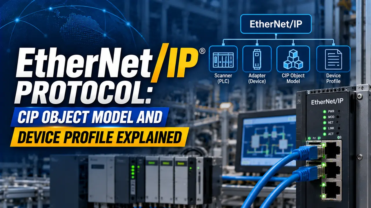
EtherNet/IP and CIP: Architecture Overview
CIP (Common Industrial Protocol) is the application-layer protocol used by EtherNet IP. CIP is also the application layer for DeviceNet (CAN bus) and ControlNet (proprietary coaxial bus), all sharing the same object model.
All three networks share the same CIP object model and services, differing only in the physical and data link layers beneath them.
An EtherNet IP device exposes its data through a structured collection of CIP Objects. Each object represents a device component — the identity, communication configuration, or a digital I/O assembly.
Accessing a device means reading from or writing to specific attributes of specific object instances.
The protocol's openness is structured: the CIP specification itself is published and available to any vendor who joins ODVA. However, all EtherNet/IP devices must be independently tested and certified by an ODVA-approved test lab before they can display the EtherNet/IP logo. This certification requirement is what gives end users confidence that a drive from Vendor A will communicate reliably with a PLC from Vendor B on the same EtherNet/IP network.
As of 2025, ODVA has more than 300 member companies producing CIP-compatible devices across EtherNet/IP, DeviceNet, and ControlNet networks.
The CIP Object Model
Objects, Instances, and Attributes
Every piece of data or configuration in an EtherNet/IP device is addressed using a three-level hierarchy: Class, Instance, and Attribute. This is the CIP logical address, written as @Class/Instance/Attribute.
Class: A category of similar objects. Class 1 is the Identity Object (device name, vendor, product code, revision). Class 4 is the Assembly Object (I/O data). Class 100 and above are vendor-specific.
Instance: A specific occurrence of a class. Class 4 Instance 1 is typically the input assembly; Instance 2 the output assembly.
Attribute: A specific data item within an instance. Attribute 1 of the Identity Object is the Vendor ID — a 16-bit integer identifying the device manufacturer as registered with ODVA.
@1/1/2 — Class 1 (Identity), Instance 1, Attribute 2 = Device Type
@1/1/7 — Class 1 (Identity), Instance 1, Attribute 7 = Product Name
@4/1/3 — Class 4 (Assembly), Instance 1, Attribute 3 = Data (input assembly data bytes)
@4/2/3 — Class 4 (Assembly), Instance 2, Attribute 3 = Data (output assembly data bytes)
@100/1/1 — Class 100 (vendor-specific), Instance 1, Attribute 1 = vendor-defined data
Service codes used with these addresses:
0x0E = Get_Attribute_Single (read one attribute)
0x10 = Set_Attribute_Single (write one attribute)
0x01 = Get_Attributes_All (read all attributes of an instance)
Many EtherNet IP devices expose dozens of attributes across multiple classes. Rather than reading each attribute individually, Get_Attributes_All on Instance 1 of the Identity Object (Class 1) returns the Vendor ID, Device Type, Product Code, Revision, Status, Serial Number, and Product Name in a single request.
Most EtherNet/IP diagnostic tools including Wireshark with the CIP dissector plugin, Studio 5000 Logix Designer, and Omron Sysmac Studio support reading the Identity Object as a standard commissioning step. Always read the Identity Object first when troubleshooting an unknown device on the network. It tells you who made the device, what type it is, and what firmware revision is running.
Required CIP Objects in Every EtherNet IP Device
Every ODVA-compliant EtherNet IP device must implement a defined set of CIP objects regardless of device type. These mandatory objects guarantee basic interoperability across vendors.
The five mandatory CIP objects are: Identity Object (Class 1), Message Router (Class 2), Connection Manager (Class 6), TCP/IP Interface Object (Class 246), and Ethernet Link Object (Class 243).
Additional required objects depend on the device profile. A drive implements the Motor Data Object and Control Supervisor Object; an I/O module implements the Discrete Input Point or Analog Input Point Object.
Explicit Messaging vs Implicit Messaging
Explicit Messaging: Request-Response over TCP
Explicit messaging is the EtherNet/IP request-response mechanism. The originator sends a CIP service request to a specific Class/Instance/Attribute address in the target.
The target responds with the requested data or an error code.
Explicit messaging uses TCP port 44818 for commissioning reads and writes, SCADA or HMI polling, and non-time-critical control commands. See the Modbus TCP guide for a comparison with the Modbus request-response model.
The encapsulation session is established by the originator sending a Register Session command to TCP port 44818. The target responds with a Session Handle a 32-bit identifier used to associate all subsequent requests in the session. Every CIP explicit message exchange that follows includes this Session Handle.
This two-layer structure (Encapsulation over TCP, CIP inside) is why a standard Ethernet analyser like Wireshark needs the CIP plugin to properly decode EtherNet IP traffic. Without the plugin, Wireshark sees only raw TCP data on port 44818. With the plugin, it decodes the full Class/Instance/Attribute addressing and service codes of every CIP message.
Implicit Messaging: Cyclic I/O over UDP
Implicit messaging is the EtherNet IP real-time I/O mechanism. Once a connection is established, data flows automatically at the configured RPI without the PLC sending a new request for each cycle.
The data content is predetermined both devices know in advance which Assembly Object instance carries the I/O data, and the data is exchanged as a fixed-size byte array.
Implicit messaging uses UDP port 2222. The PLC's I/O scanner establishes a Class 1 connection to the target device at startup.
After that, the target sends input data to the scanner at every RPI interval and the scanner sends output data to the target at every RPI interval. The two streams are independent.
The RPI for a typical EtherNet IP I/O connection is 2 to 20 ms. Motion control can use RPIs as low as 0.5 ms on a well-designed network.
Setting an unnecessarily fast RPI generates more UDP broadcast traffic on the EtherNet/IP network. On a switch with many I/O connections all running at the fastest possible RPI, the aggregate UDP traffic can approach or exceed the available bandwidth of a 100 Mbit/s switch port.
A well-designed EtherNet/IP network engineering calculation checks the aggregate implicit messaging bandwidth at each switch port before commissioning. For a PLC managing 50 I/O modules at a 2 ms RPI with 32-byte assemblies, the aggregate input traffic alone is approximately 50 × 32 bytes × 500 packets/s × 8 bits = 6.4 Mbit/s — manageable on a 100 Mbit/s port, but worth checking when other traffic (HMI, historian, engineering workstation) shares the same port.
Device Profiles and the EDS File
What Is a Device Profile?
A CIP device profile is an ODVA specification defining which CIP objects, attributes, and services a device category must implement.
Device profiles ensure that a PLC from any vendor can talk to a drive, I/O module, or sensor from any other vendor without custom code.
Common EtherNet/IP device profiles include: AC Drive, DC Drive, Generic Device, Digital I/O Module, Analog I/O Module, Position Controller, Valve Actuator, and Safety Device (for CIP Safety applications).
Each profile specifies the mandatory objects, required Assembly instances, and I/O data format that conforming devices must expose.
The EDS File: Electronic Data Sheet
An EDS (Electronic Data Sheet) file is a text file from the device manufacturer describing the CIP object model, I/O assembly formats, and configurable parameter ranges.
The EDS is installed into the PLC programming software and tells it what objects and attributes the device exposes.
Without the EDS file, the PLC programmer must manually enter the Class/Instance/Attribute address of every data point. With the EDS installed, the programming software displays the device parameters by name.
Device manufacturers release new firmware versions that may add parameters, change attribute numbering, or modify Assembly instance formats. An EDS file from firmware version 1.0 may not correctly describe the same device running firmware version 2.0.
The Device Type and Revision attributes in the Identity Object (Class 1, Instance 1, Attributes 2 and 3) are the authoritative source for firmware revision. Compare these against the EDS file revision before relying on the EDS for commissioning. Most ODVA-certified EtherNet/IP scanners will warn you if the EDS revision does not match the device revision reported by the Identity Object.
EtherNet/IP vs Modbus TCP vs PROFINET: Protocol Comparison
| Parameter | EtherNet/IP | Modbus TCP | PROFINET |
|---|---|---|---|
| Application layer | CIP (Common Industrial Protocol) — object-based, service-oriented | Modbus PDU — function code and register-based, no object model | PROFINET Application Layer — device profile and GSD-file-based |
| Real-time I/O | Implicit messaging (Class 1 connection) over UDP. RPI configurable from 0.5 ms to seconds. | Polling only. No dedicated real-time channel. Speed depends on poll cycle. | Cyclic data exchange (RT or IRT). IRT achieves under 1 ms with hardware timestamping. |
| Configuration messaging | Explicit messaging (Class 3 connection) over TCP port 44818. Full CIP object addressing. | Modbus read/write function codes over TCP port 502. Register-based only. | Acyclic communication via DCE/RPC (device configuration) and DCP (discovery). |
| Device description file | EDS file (text format, ODVA specification). Installed in programming software. | No standard device description file. Data mapping is manual or application-specific. | GSD file (XML format, GSDML). Installed in engineering tool (TIA Portal, etc.). |
| Addressing model | CIP Class/Instance/Attribute (object-based). Vendor-neutral across ODVA members. | Coil number and register number (flat address space). Vendor defines meaning of each register. | Slot/subslot/index (module-based). Device structure defines the address space. |
| Physical layer | Standard IEEE 802.3 Ethernet. Cat5e/Cat6, standard managed switches, no hardware modification required. | Standard IEEE 802.3 Ethernet. Same hardware as EtherNet/IP. | Standard IEEE 802.3 Ethernet. IRT requires PROFINET-capable switches for hardware timestamping. |
| Safety variant | CIP Safety (over EtherNet/IP). IEC 61508 SIL 2 to SIL 3 certified. Uses black channel safety transport. | No standard safety variant. Modbus safety applications use external safety systems. | PROFIsafe. IEC 61508 SIL 3 certified. Widely used in European machine safety applications. |
| Dominant geography | North America, Japan (Omron, Yaskawa). Worldwide for Rockwell/Allen-Bradley systems. | Worldwide. Dominant for third-party device integration due to simplicity. | Europe. Standard for Siemens systems worldwide. |
| Managing organisation | ODVA (Open DeviceNet Vendors Association). Over 300 members. | Modbus Organisation. Open specification, no membership required. | PI (PROFIBUS and PROFINET International). Over 1,400 member companies. |
EtherNet/IP Bandwidth and RPI Planning Tool
Watch: EtherNet/IP Industrial Protocol — Basics and Architecture (2024)
EtherNet/IP Questions Engineers Ask
Related Articles on This Site
- OPC UA Explained: Architecture and Industrial Use
- Communication Protocols in DCS Systems
- MQTT Protocol for Industrial IoT
- SCADA Communication Protocol Overview
- RS-232 vs RS-485 in Industrial Automation
External References
- EtherNet/IP Technology Overview | ODVA (2024)
- EtherNet/IP Protocol Overview | Real Time Automation (2024)
What We Learn Today
- EtherNet/IP carries CIP (Common Industrial Protocol) over standard TCP and UDP on unmodified Ethernet hardware. The CIP object model addresses every device data point using a three-level hierarchy — Class, Instance, and Attribute. Explicit messaging (TCP port 44818) handles request-response configuration and monitoring. Implicit messaging (UDP port 2222) handles real-time cyclic I/O at a configurable Requested Packet Interval (RPI).
- CIP device profiles define which objects a specific category of device must implement, ensuring that a PLC from any ODVA member company can communicate with a drive or I/O module from any other member without custom code. The EDS file provided by each device manufacturer maps those objects to human-readable parameter names in the PLC programming software.
- EtherNet/IP is dominant in North America and Rockwell Automation systems, while PROFINET dominates Europe and Siemens systems, and Modbus TCP remains the most widely used protocol for third-party device integration across all regions. All three use standard Ethernet hardware at the physical layer, but differ significantly in their application-layer object models, device configuration mechanisms, and real-time I/O performance characteristics.