MSG Instructions in PLC Programming: 4 Vital Facts

Share:
Instrumentation
MSG Instructions in PLC Programming: 4 Vital Facts

A single MSG block sitting quietly in a rung can move a recipe between two controllers, or it can silently freeze a scan, overwrite another message in flight, and leave a program acting on data that never actually arrived.

Understanding MSG Instructions in PLC Programming properly means knowing both the configuration mechanics and the failure modes that only show up once the system is running for real.

MSG Instructions in PLC Programming Explicit Messaging CIP Messaging Cache Connections

MSG Instructions in PLC Programming move data between controllers over a network rather than a local backplane, and getting the message type, triggering logic, and status bits right is what separates a reliable exchange from a hidden production headache.

An MSG instruction is the tool a Logix based controller uses to explicitly ask another device for data, or push data to it, instead of relying on the automatic implicit exchange that happens over a scheduled connection.

That flexibility is also the catch, since an explicit message consumes scan time, a communication resource, and a chunk of program logic that has to track when it actually finished and whether it actually succeeded.
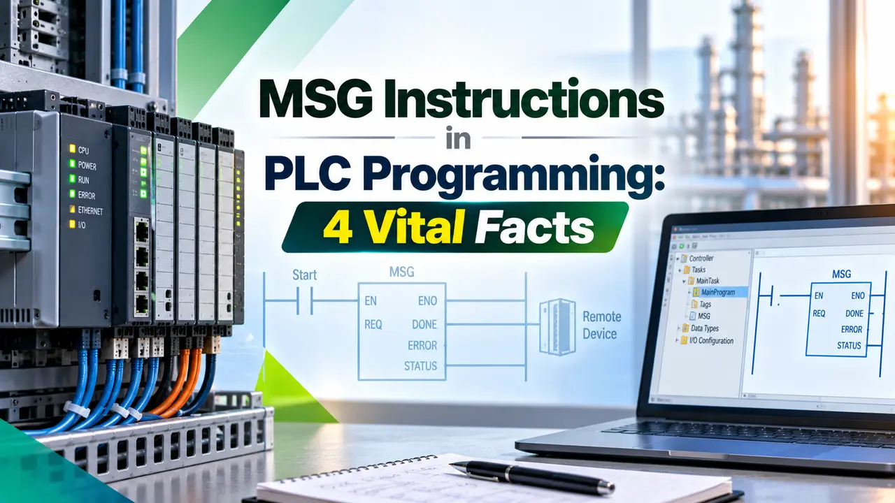
MSG Instructions in PLC Programming
Advertisement

4 Message Types Behind MSG Instructions in PLC Programming

1
CIP Data Table Read/Write
Moves a block of tag data between two Logix controllers using the Common Industrial Protocol, the most common type for PLC to PLC exchange.
2
CIP Generic
Sends a raw CIP service request to a target device, useful for drives, third party modules, or anything outside a simple tag read.
3
PLC5/SLC Typed & Word Range
Bridges a modern controller back to a legacy PLC5 or SLC processor, matching its older addressing and data table structure.
4
Block Transfer Read/Write
Carries larger blocks of data to and from legacy remote I/O style devices that still expect a block transfer format.

Picking the wrong type is one of the most common early mistakes, since a PLC5 typed read aimed at a modern ControlLogix tag simply fails rather than quietly falling back to something that works.

Advertisement

Configuring the Instruction: Tabs Worth Understanding

Configuration Tab
Sets the message type, service code, and the source or destination element
Communication Tab
Defines the path to the target device, including slot, IP address, or bridge hops
Tag Tab
Confirms the local and remote tags share a matching data type and array length
Cache Connections
Keeps the connection open between sends instead of rebuilding it every scan

A mismatched data type between the Tag tab and the actual remote tag is one of the quieter configuration mistakes, since it can produce a completed message carrying garbled or truncated values instead of an outright error.

Status and Error Bits That Tell the Real Story

BitWhat It Actually Means
EN (Enable)The rung enabling the instruction is currently true
ST (Start)The message has been accepted and handed off to the communication system
DN (Done)The message completed successfully and the transfer is finished
ER (Error)The message failed, with an accompanying error code explaining why
TO (Timeout)The target device never responded within the configured time window
EW (Error Warning)Marks that an error code is present and worth checking before retriggering

A program that only checks DN and never checks ER or TO is effectively flying blind, since it treats a silently failed message the same way it treats one that actually succeeded.

Triggering Habits That Avoid Duplicate Sends

1
Trigger on a one shot rung transition rather than a continuously true condition, so the instruction fires once per event.
2
Wait for DN or ER before allowing the same MSG instruction to fire again, rather than retriggering on a timer alone.
3
Use a dedicated one shot instruction ahead of the MSG rung instead of relying on the instruction's own internal edge detection.
4
Reset the enable bit explicitly after an error, since some faults leave the instruction in a state that blocks a clean retry.

Connected vs Unconnected Messaging

Connected Messaging

Reserves a dedicated resource for the life of the message, giving more predictable timing at the cost of holding that resource open.

Unconnected Messaging

Shares a common message pool across the whole controller, using less overhead but competing with every other unconnected request in flight.

Choosing connected messaging for a frequent, time sensitive exchange and unconnected for an occasional one is usually the right split, rather than defaulting to whichever the wizard happens to suggest first.

Tip
A good rule of thumb is to enable Cache Connections when an MSG instruction executes more often than roughly once every 60 seconds, keeping the connection open instead of rebuilding it on every single send. Modern ControlLogix and CompactLogix controllers commonly support on the order of 256 cached connections and a similar number of simultaneous unconnected messages, though the exact figure is firmware and hardware dependent and should be checked against the specific controller in use.

Where MSG Instructions in PLC Programming Get Used on the Floor

1
Exchanging production counts or interlock status directly between two peer PLC controllers on the same line.
2
Reading or writing a tag on a remote controller without building a permanent scheduled connection for occasional data.
3
Pushing a recipe or batch parameter set out to several machine controllers from a central line controller.
4
Bridging a modern Logix system back to legacy PLC5 or SLC hardware still running elsewhere on the plant floor.
5
Handshaking between two machines during a handoff, confirming each side is ready before releasing product downstream.
Did You Know
A cached connection that is never actually reused still consumes a slot from the controller's limited connection pool. On a busy system running close to its commonly cited 256 connection figure, a handful of forgotten one time messages left on Cache Connections can quietly crowd out the connections that genuinely need to stay open.

Common Error Codes Worth Recognizing

When the ER bit sets, the instruction also reports a numeric error code, and recognizing the common ones saves a lot of guesswork during commissioning and troubleshooting.

Error CodeWhat It Usually Points To
16#0001Connection failure, often a wrong path or a device that is offline
16#0004Invalid segment or path syntax entered on the Communication tab
16#0005Path destination unknown, typically a wrong slot or IP address
16#0203Connection timed out, matching a set TO bit on the instruction
16#0301No available connection resources left in the controller's pool

That last code is exactly why watching Cache Connections usage matters, since a controller that quietly runs out of connection resources starts failing brand new MSG instructions rather than the ones already established.

A program that logs the error code alongside a timestamp whenever ER sets gives a technician something concrete to search against, rather than a vague complaint that a message occasionally fails for no obvious reason.

Risks That Turn a Working MSG Instruction Into a Problem

1
Scan time blocking, where a message configured to execute in blocking mode consumes CPU time every scan while it stays active.
2
Silent use of stale data, since a program that never checks a timestamp or a data valid bit can keep acting on an old reading.
3
Loss of determinism, as packet routing, switch queues, and target CPU load all make completion timing genuinely unpredictable.
4
Message collision, where two messages sharing a control structure or path at once mix up status bits or overwrite each other's data.
5
Redundancy switchover risk, where a retry gets lost during a primary to secondary failover, or control bits stay corrupted for a few scans.
6
Security exposure, since an MSG instruction is trusted implicitly with no native authentication and functions like a remote command with no audit trail.

None of these risks mean MSG instructions in PLC programming should be avoided, they mean the instruction deserves the same disciplined error checking given to any other communication path in the system.

Advertisement

A Practical Checklist Before Trusting an MSG Instruction in Production

1
Confirm the program checks EN, DN, ER, and TO together, never just DN alone, before treating a message as genuinely successful.
2
Avoid sharing one control structure across two messages that could fire close together, since that is a common cause of collision.
3
Size Cache Connections deliberately against the actual controller limit rather than enabling it by default on every instruction.
4
Test the exact failover behavior on a redundant system, since a message left mid transfer during a switchover rarely behaves cleanly.
5
Treat every MSG path as a command channel that deserves the same access control review given to any other write path into the system.

A short commissioning review that walks through each of these points before a new MSG instruction goes live catches a surprising share of the problems that would otherwise surface months later as an intermittent nuisance.

Documentation Habits That Save the Next Troubleshooting Session

An MSG instruction rarely fails the day it is commissioned, it tends to fail months later when a network changes, a device gets swapped, or a controller firmware update shifts a default timeout somewhere in the path.

1
Record the intended communication path in the rung comment, not just in a configuration screen nobody revisits later.
2
Note why a message type was chosen, especially when a legacy PLC5 or SLC bridge was involved in that decision.
3
Log the expected send frequency next to the Cache Connections setting, so a future change does not silently break the assumption.
4
Keep a short list of every device an MSG instruction talks to, since that list is the first thing a technician needs during an outage.

None of this documentation takes long to write the first time, and it consistently turns a multi hour troubleshooting session into a five minute check against a known path and a known configuration.

Watch: PLC Allen Bradley's MSG Instruction

MSG Instructions in PLC Programming Questions Engineers Ask

What is the most common MSG instruction type used between two Logix controllers?
CIP Data Table Read/Write is the most common choice for moving tag data directly between two modern Logix processors.
Should a program check only the Done bit after sending a message?
No, checking Error and Timeout bits alongside Done is essential, since a failed message never sets Done at all.
When should Cache Connections be enabled on an instruction?
Enable it when the message executes more often than roughly once a minute, avoiding the overhead of rebuilding the connection.
Why does message collision happen between two MSG instructions?
It happens when two messages share the same control structure or communication path and fire close together in time.
Can an MSG instruction bridge a modern controller to a legacy PLC5?
Yes, the PLC5 and SLC typed read and write types exist specifically to bridge back to that older hardware.
Does an MSG instruction include any built in authentication?
No, it is trusted implicitly by the receiving device, which is why access control review matters for every message path.

Related Articles on This Site

External References

Advertisement

What We Learn Today

  • MSG Instructions in PLC Programming cover four main message types, from CIP Data Table Read/Write to legacy block transfer formats.
  • Checking EN, DN, ER, and TO together is what separates a program that truly knows a message succeeded from one that only assumes it did.
  • Real risks like message collision, stale data, and unauthenticated commands deserve the same review given to any other communication path.
I hope you like above blog. There is no cost associated in sharing the article in your social media. Thanks for reading!! Happy Learning!!

Leave a Reply

Your email address will not be published. Required fields are marked *