
PLC math instructions let a Ladder Logic program perform arithmetic directly on register values. Without them, a PLC can only switch outputs on and off.
With them, it can calculate totals, convert sensor signals, compute flow rates, and check engineering limits. These PLC math instructions are essential for any calculation beyond simple on/off control.
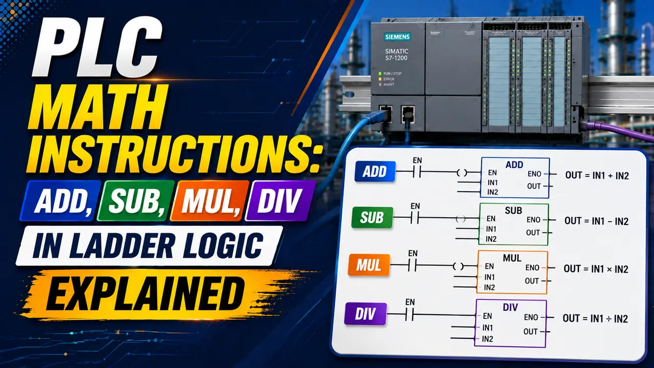
This guide covers the four core PLC math instructions -- ADD, SUB, MUL, DIV -- with rung examples, data type rules, overflow handling, and a live PLC math instruction calculator.
PLC math instructions execute only when the rung condition is true. The result goes into a destination register. Data type, register size, and overflow behaviour must be understood before writing any arithmetic rung.
PLC Math Instructions in Ladder Logic
Ladder Logic was originally designed for relay replacement. It handles contact logic brilliantly.
But process control needs numbers. That is where PLC math instructions come in -- they bring arithmetic into the Ladder Logic world.
These four PLC math instructions -- ADD, SUB, MUL, and DIV -- are the building blocks for all arithmetic in Ladder Logic. Click any instruction name to see what it does.
The 4 PLC Math Instructions Explained with Ladder Rung Examples
ADD -- Addition Instruction
ADD reads the values in Source A and Source B, adds them together, and writes the result to the Destination register. Like all PLC math instructions, ADD only executes when the rung condition is true.
The Destination register must be a different address from the Source registers in most platforms, though some allow in place addition. Both Sources can be either register addresses or immediate constant values.
Practical use of the ADD PLC math instruction: accumulating batch counts, adding a trim offset to a setpoint, summing energy readings from multiple sub-meters. See the PLC counter instructions article for how counters use ADD internally.
SUB -- Subtraction Instruction
The SUB PLC math instruction subtracts Source B from Source A. The order matters: Source A is the minuend (the number being subtracted from). Source B is the subtrahend (the number being taken away).
A negative result is valid in a signed register. If you subtract a larger number from a smaller one, the Destination will hold a negative value. Unsigned registers (UINT) cannot hold negative values and will wrap around, producing a large positive result instead.
Practical use: calculating remaining quantity in a batch, computing error (setpoint minus process variable), finding a tare-corrected weight (gross weight minus tare weight). The error term in a manual PID calculation uses SUB for the SP minus PV step.
MUL -- Multiplication Instruction
MUL multiplies Source A by Source B and places the result in the Destination. Multiplication is where overflow becomes a real risk.
Multiplying two 16-bit INT values can produce a result up to 32,767 squared -- just over one billion. A 16-bit register cannot hold this.
Always use a DINT or REAL destination register when multiplying INT values, or when the result may exceed the source register size.
Practical use: scaling raw ADC counts to engineering units, converting between measurement units, calculating flow rate from pulse count and K factor.
See the flow meter K factor guide and the PLC memory addressing guide for related detail.
DIV -- Division Instruction
The DIV PLC math instruction divides Source A by Source B. Two rules are critical: the data type of the Destination determines whether the result is truncated or fractional, and division by zero causes a fatal fault on most PLC platforms.
Integer division truncates toward zero. For a PLC math instruction using INT: 7 / 2 = 3, and 9 / 4 = 2.
If you need the fractional part, convert both sources to REAL before dividing and use a REAL Destination register.
Division by zero protection: always check that Source B is not zero before a DIV instruction.
Use a compare rung (GT or NEQ) to gate it with a contact. If Source B can ever be zero, the DIV must be protected or the PLC will fault.
PLC Math Instruction Data Types and Overflow Rules
| Data Type | Size | Range | Use With | Risk |
|---|---|---|---|---|
| INT (Integer) | 16-bit signed | minus 32,768 to 32,767 | ADD, SUB with small values | Overflow if result exceeds 32,767 |
| UINT (Unsigned Int) | 16-bit unsigned | 0 to 65,535 | ADD with positive values only | Cannot hold negative results from SUB |
| DINT (Double Int) | 32-bit signed | minus 2,147,483,648 to 2,147,483,647 | ADD, SUB, MUL for large values | Still overflows if MUL result exceeds 2.1 billion |
| REAL (Float) | 32-bit IEEE 754 | approx. plus/minus 3.4 x 10 to the 38 | DIV for fractional results, scaled engineering values | Precision limited to 7 significant digits; compare REAL values with tolerance, not exact equality |
| LREAL (Long Float) | 64-bit IEEE 754 | approx. plus/minus 1.8 x 10 to the 308 | High-precision scientific calculations | Not supported on all PLC platforms |
Worked Example: PLC Math Instruction Chain for Scaling a 4 to 20 mA Signal
A pressure transmitter outputs 4 to 20 mA for 0 to 100 bar. The PLC reads this as a raw ADC count from 0 to 4095. The PLC math instruction chain below converts the raw count to bar.
Scale Formula: Pressure = (RawADC minus Offset) x Span / ADC_Max
PLC Math Instruction Result Calculator
PLC Math Instructions: Full Comparison Table
| Instruction | Operation | Result Register Type | Key Risk | Common Application |
|---|---|---|---|---|
| ADD | A + B | Same as inputs or larger | Overflow if sum exceeds register size | Accumulating totals, adding offsets, summing sub-meter readings |
| SUB | A minus B | Signed (allows negative) | Negative result in unsigned register wraps around | Error calculation, remaining quantity, tare subtraction |
| MUL | A x B | Use DINT or REAL | Result can be much larger than either input | Unit conversion, scaling ADC counts, flow calculation |
| DIV | A / B | REAL for fractional result | Division by zero causes major fault | Averaging, rate calculation, percentage calculation |
Real-World Applications Using PLC Math Instructions
Batch Totalising
ADD accumulates the batch count each completed cycle.
A SUB rung subtracts the total from the target to give remaining quantity. When the SUB result reaches zero, a compare triggers the end of-batch output. Uses the same register principles as PLC counter instructions and the shift register.
Engineering Unit Scaling
MUL and DIV convert raw ADC input counts to engineering units (bar, °C, m3/h). The formula requires multiplying by the engineering span and dividing by the ADC full scale count. REAL registers are used throughout to preserve fractional values.
Timer Setpoint Calculation
A MUL PLC math instruction converts a setpoint entered in minutes to milliseconds (multiply by 60,000) for use as a timer preset. See PLC timer instructions for how the preset value is used in TON and TOF timers.
Average Calculation
ADD accumulates samples into a sum register. A DIV PLC math instruction divides the sum by the sample count to give the rolling average.
The sample count must be checked NEQ 0 before the DIV runs. Used for flow averaging and temperature smoothing.
Watch: PLC Math Instructions in Ladder Logic
PLC Math Instructions Questions
External References
What We Learn Today
- PLC math instructions (ADD, SUB, MUL, DIV) execute every scan the rung condition is true
- ADD: result = A + B. Use DINT when accumulated values may exceed 32,767
- SUB: result = A minus B. Order matters. Negative results need a signed register
- MUL: result = A x B. Use DINT or REAL destination -- products can far exceed input size
- DIV: result = A / B. Integer truncates -- use REAL for fractional results. Always guard against division by zero
- Chain PLC math instructions rung by rung using intermediate registers -- never on the same rung