
Ultrasonic flow meters offer non intrusive measurement with no pressure drop and no moving parts.
When they malfunction, the fault almost always lies in one of three areas: the acoustic signal path, the installation geometry, or the parameter settings entered at commissioning.
This guide covers seven common ultrasonic flow meter faults for both transit time and Doppler types, with root causes, corrective actions, and an interactive diagnostic tool.
Signal strength is the first parameter to check on any ultrasonic fault.
A signal quality below the manufacturer's minimum (typically 60 to 70%) means the reading cannot be trusted, regardless of what the display shows.
Transit Time vs Doppler: Which Faults Apply to Which Type
The two ultrasonic measurement principles have different fault modes.
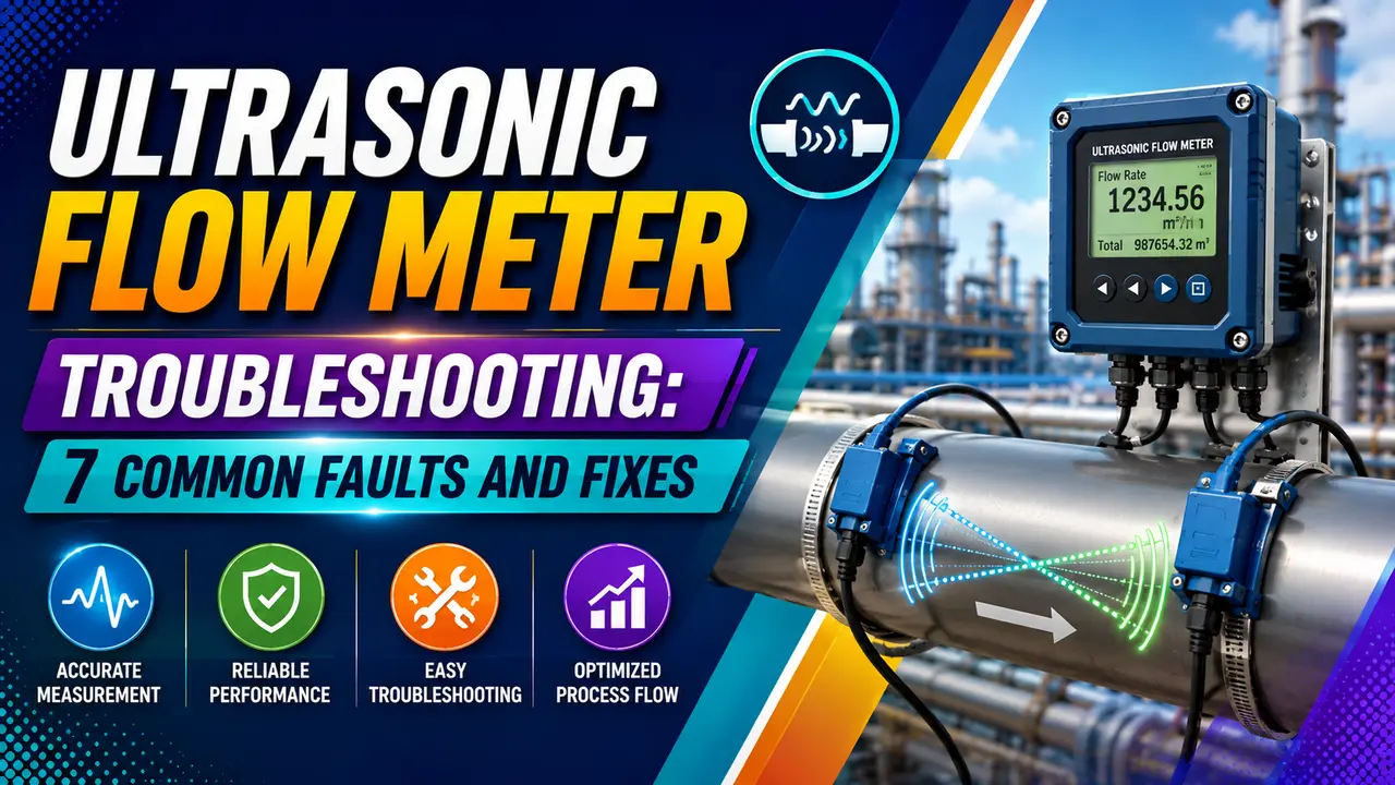
Transit time meters measure travel-time difference of pulses sent with and against the flow -- they require clean, homogeneous fluid. Doppler meters measure frequency shift of ultrasound reflected by particles or bubbles -- they require those scatterers to be present.
| Fault Type | Transit Time | Doppler |
|---|---|---|
| No signal / signal loss | Applies -- empty pipe, wrong fluid, bad coupling, scale on pipe wall | Applies -- but less sensitive; particles in fluid help maintain signal |
| Low signal strength | High sensitivity -- clean fluid required; any gas or solid content degrades signal | Low sensitivity -- gas or solids actually required for operation |
| Reading high due to gas entrainment | Applies -- gas bubbles scatter the beam, causing over-reading or signal loss | Does not apply -- Doppler reads gas bubbles as reflectors, may over-read velocity |
| Reading zero with flow present | Applies -- zero calibration error or pipe parameter mismatch | Applies -- no particles in clean fluid means no reflection and no reading |
| Erratic output near pumps or elbows | Applies -- swirl and asymmetric profile corrupt transit time difference | Applies, less severe -- Doppler is less sensitive to profile distortion |
| Reading drifts with temperature | Applies -- speed of sound in fluid is temperature-dependent; must be compensated | Applies, less severe -- Doppler frequency shift less sensitive to sound velocity |
7 Common Faults: Symptoms, Causes and Fixes
What It Looks Like
- Signal quality drops to zero or near zero
- Error code on display (E1, "No Signal", or similar)
- Output holds at last value, goes to 4 mA or 22 mA depending on failsafe setting
Root Causes
- Pipe is empty or partially filled with gas
- Heavy internal scale, fouling, or tuberculation blocking acoustic path
- Clamp on: insufficient coupling gel or gel dried out
- Liner debonding in lined pipe (air gap between liner and steel)
- Wrong pipe material or wall thickness entered -- transducer spacing calculated incorrectly
- Transducer cable damaged or connector corroded
Corrective Actions
- Confirm pipe is full and pressurised -- vent high points
- Re apply coupling gel for clamp on types; use ultrasonic couplant, not grease
- Check pipe parameters (bore, wall thickness, pipe material) against actual pipe
- Inspect transducer cable and connector for damage or moisture ingress
- Try an alternative transducer mounting location on a different pipe section
- Use thickness gauge to check for internal scale at the clamp on location
What It Looks Like
- Signal quality fluctuates between 30 and 70%
- Reading drops out intermittently and recovers
- Signal quality worsens at higher flow rates
Root Causes
- Entrained gas bubbles scattering the beam (transit time type)
- Partially filled pipe at low flow with gas interface passing through beam
- Clamp on gel drying at high ambient temperature
- Clamp on: pipe vibration loosening transducer contact
- Mild internal scale -- sufficient signal at low flow, lost at high flow due to increased turbulence
Corrective Actions
- Check for entrained gas -- confirm the process is genuinely single phase liquid at this point
- Move clamp on transducers to a location where the pipe is confirmed full at all flow rates
- Use a permanent coupling compound (epoxy or solid coupling pad) instead of gel for high temperature applications
- Check and retighten clamp on mounting hardware
- Assess internal pipe condition with a thickness gauge or radiography at the transducer location
What It Looks Like
- Meter reads 5 to 25% above or below a reference meter
- Error is proportional to flow rate
- Zero reading is correct when flow stops
Root Causes
- Incorrect pipe bore or wall thickness entered -- changes the acoustic path length calculation
- Wrong pipe material entered -- affects sound velocity in the pipe wall
- Wrong speed of sound for the fluid -- fluid temperature or composition changed
- Insufficient upstream straight pipe -- distorted velocity profile is not representative of true average
- Wrong installation mode (diagonal vs midpoint vs multiple traversal)
Corrective Actions
- Measure actual pipe OD and wall thickness with callipers and ultrasonic thickness gauge -- do not rely on nominal pipe schedule
- Verify pipe material (304SS vs carbon steel have different acoustic velocity)
- Enter fluid sound velocity for actual operating temperature -- check manufacturer's fluid database or calculate from fluid properties
- Measure upstream and downstream straight pipe runs -- compare to meter specification
- Verify transducer spacing matches the value calculated by the meter's setup wizard for the measured pipe dimensions
What It Looks Like
- Meter displays zero flow with flow confirmed by pressure drop or other meter
- Signal quality may be good -- this is not a signal loss fault
- Totaliser does not accumulate
Root Causes
- Zero calibration performed while flow was not actually stopped -- zero offset is now baked in
- Low flow cutoff set too high -- suppressing real low flow signal
- Both transducers firing simultaneously (wiring swap) -- no transit time difference to measure
- Doppler type: fluid is too clean for reflectors -- no particles or bubbles to reflect signal
Corrective Actions
- Re perform zero calibration with confirmed zero flow (valve closed, pressure equalised, flow confirmed stopped by independent means)
- Reduce low flow cutoff setting and re-test at actual low flow condition
- Swap transducer A and B wiring and re-test -- if reading appears, original wiring was reversed
- For Doppler type: confirm fluid has adequate suspended solids or gas content for reflection
What It Looks Like
- Reading fluctuates more than expected for the actual flow variation
- Signal quality is good but reading is noisy
- Problem worsens at higher flow rates
Root Causes
- Turbulent or swirling velocity profile from insufficient straight pipe upstream
- Cavitation from a partially open valve just upstream
- Pulsating flow from a reciprocating pump
- Flow profile swirl from two elbows in different planes upstream
Corrective Actions
- Increase upstream straight pipe -- minimum 10D after an elbow, 20D after a partially open control valve, 50D after a pump
- Relocate the meter to a better straight pipe section -- this is often the only effective fix for severe profile distortion
- Use a multipath ultrasonic meter (4 or 6 paths) which averages across paths and is less sensitive to profile distortion
- Fit a flow conditioner (tube bundle or perforated plate) upstream to flatten the profile
What It Looks Like
- Reading shifts when process temperature changes, even with steady flow
- Error is larger at extreme temperatures (hot or cold)
- Signal quality remains good throughout
Root Causes
- Speed of sound in the fluid changes with temperature but the meter uses a fixed value
- No temperature input connected -- meter uses a fixed default fluid sound velocity
- Transducer spacing changes with thermal expansion of the pipe at extreme temperatures
- Clamp on coupling gel changing properties with temperature
Corrective Actions
- Connect a temperature input (RTD or thermocouple) to the meter for automatic sound velocity compensation
- Enter the correct fluid sound velocity versus temperature table in the meter configuration
- For clamp on on hot pipes, use a high temperature coupling compound or standoff mounting
- Recalculate and verify transducer spacing at operating temperature (not ambient)
What It Looks Like
- Signal quality suddenly drops on a meter that previously worked well
- Moving the transducers a few centimetres along the pipe partially restores signal
- Different signal quality readings at different axial locations
Root Causes
- Internal scale (calcium carbonate, magnetite, biofilm) forming over time
- Plastic liner debonding from the steel pipe wall -- air gap between liner and steel attenuates the signal
- External corrosion or pitting at the transducer location causing poor acoustic contact
- Original installation on a poor pipe section (weld, fitting, or wall variation)
Corrective Actions
- Measure pipe wall thickness at the transducer location using a separate ultrasonic thickness gauge -- compare to nominal and to upstream/downstream
- If scale is confirmed, relocate transducers to a clean section of pipe or consider an inline insertion meter
- Inspect pipe externally for corrosion -- clean and degrease the surface before reinstalling transducers
- For lined pipe: check with the liner manufacturer whether debonding has been reported on this service -- consider a different measurement technology
Interactive Diagnostic Tool
Commissioning Checklist for Ultrasonic Flow Meters
| Check | Requirement | How to Verify |
|---|---|---|
| Pipe dimensions | Actual OD, wall thickness, and material -- not nominal schedule | Pi tape for OD; ultrasonic thickness gauge for wall thickness; mark material grade on pipe |
| Straight pipe runs | Minimum 10D upstream, 5D downstream of all disturbances | Count diameters from the nearest elbow, valve, reducer, or branch -- add 20D for partially open valves |
| Transducer spacing | Matches the value calculated by the meter's setup wizard for the measured dimensions | Measure physical distance between transducer centres; compare to calculated spacing in the meter display |
| Coupling gel / compound | Ultrasonic couplant (not grease, silicone, or oil) applied to full face of transducer | Check signal quality before and after applying couplant -- quality should jump from near zero to above 80% |
| Fluid sound velocity | Entered at actual operating temperature -- not 20°C default | Check meter configuration against fluid property table or calculate from temperature using meter's built in wizard |
| Signal quality | Above 60% (some manufacturers: above 70%) at operating flow rate | Read signal quality parameter from meter display at actual operating conditions -- not just at zero flow |
| Zero calibration | Performed with pipe full, zero flow confirmed at a closed valve | Isolate with a fully closed block valve; wait for pressure equalisation; perform zero from meter menu |
| Loop check | 4 mA at zero flow, 20 mA at calibrated full-scale flow, correct value at DCS | Verify with a loop calibrator and confirm DCS tag reads correct engineering unit value |
Watch: Ultrasonic Flow Meter Troubleshooting
Ultrasonic Flow Meter Troubleshooting Questions
External References
- Daniel 3410 Ultrasonic Flow Meter Technical Documentation -- Emerson
- Ultrasonic Flow Meter Selection and Troubleshooting -- Krohne
What We Learn Today
- Signal quality is the first parameter to check -- below 60% makes any reading unreliable
- Transit time requires clean fluid; Doppler requires scatterers -- using the wrong type is the first setup mistake
- Always measure actual pipe OD and wall thickness -- nominal pipe schedule causes span errors
- Fluid sound velocity must be entered at operating temperature -- the default 20°C value causes drift as temperature changes
- Zero calibration must be done with pipe full of process fluid and zero flow confirmed at a closed valve
- Straight pipe runs of 10D upstream and 5D downstream are the minimum -- double these near pumps or control valves