
A plate heat exchanger transfers heat between two fluid streams through corrugated metal plates.
The fluids flow in alternating channels on opposite sides of each plate, never mixing. The corrugated surface creates turbulence that dramatically improves heat transfer compared to smooth-bore tubes.
This guide covers the working principle, LMTD and Q formulas, PHE types, instrumentation requirements, and two interactive calculators for heat duty and LMTD.
The plate heat exchanger achieves a much closer temperature approach than a shell and tube design.
Approach temperatures of 1 to 3°C are achievable in a PHE versus 5 to 10°C in a shell and tube unit of the same footprint -- more heat recovered from the same differential.
How a Plate Heat Exchanger Works
The PHE consists of corrugated plates clamped between a fixed frame plate and a movable pressure plate.
Gaskets between the plates direct hot fluid to alternate channels and cold fluid to the channels between. Hot and cold streams flow on opposite sides of the same plate simultaneously.
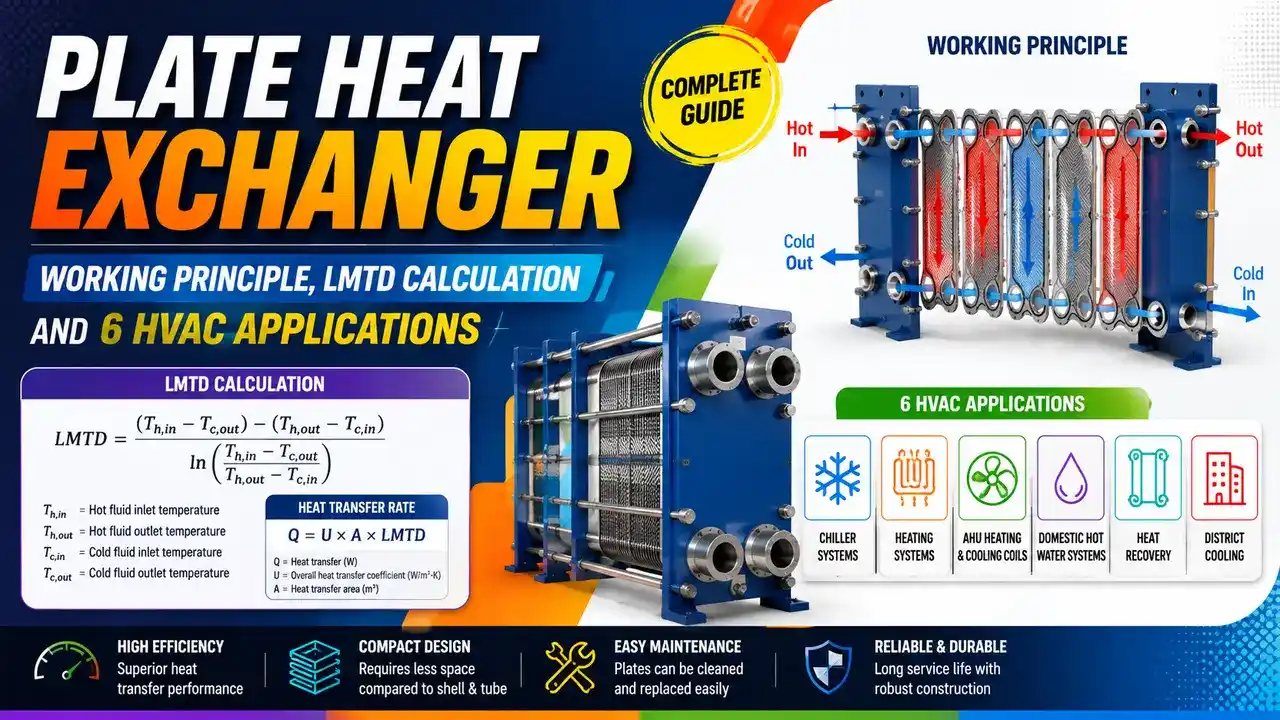
In counterflow, each portion of the cold stream always contacts the hottest available part of the hot stream.
This gives the maximum possible temperature driving force across the entire exchanger, which is why PHEs achieve closer temperature approaches than parallel flow designs.
Counterflow arrangement: hot and cold streams flow in opposite directions for maximum temperature driving force
Heat resistance has three layers in series: hot side film, plate material, and cold side film.
The corrugated pattern increases turbulence, breaking the boundary layer and raising U to 3,000 to 6,000 W/m²·K for water to water service. A comparable shell and tube achieves 800 to 1,500 W/m²·K.
Key Heat Transfer Formulas
ṁ = mass flow rate of the fluid (kg/s)
Cp = specific heat capacity (J/kg·K) -- water: 4,186 J/kg·K
ΔT = temperature difference across the exchanger on one side (K or °C)
Apply to both sides: Q_hot = Q_cold in steady state (heat balance)
A = total heat transfer area of all plates (m²)
LMTD = Log Mean Temperature Difference (°C or K)
LMTD = (ΔT₁ − ΔT₂) / ln(ΔT₁ / ΔT₂)
Counterflow: ΔT₁ = T_hot_in − T_cold_out, ΔT₂ = T_hot_out − T_cold_in
Parallel flow: ΔT₁ = T_hot_in − T_cold_in, ΔT₂ = T_hot_out − T_cold_out
PHE Calculators: Heat Duty and LMTD
PHE Construction Types
Gasketed Plate and Frame
Plates held by bolted frame with rubber gaskets between each plate. Can be opened for cleaning and plates added or removed to change capacity. Maximum pressure: typically 25 bar. Suitable for viscous fluids and duties requiring periodic mechanical cleaning.
Brazed Plate Heat Exchanger (BPHE)
Stainless steel plates brazed together with copper or nickel. No gaskets, no frame -- extremely compact. Cannot be opened for cleaning. Suitable for refrigerant service (evaporators and condensers in chiller units) and clean water duties. Maximum pressure: up to 45 bar.
Welded Plate Heat Exchanger
Plates welded together in pairs, with gaskets only between the welded pairs. Handles higher pressures and temperatures than gasketed types. Suitable for aggressive chemicals, high-temperature process streams, and applications where gasket compatibility is a concern.
Semi Welded (Twin Plate)
Alternating channels -- one side welded (for refrigerant or aggressive fluid), the other side gasketed (for water or brine). Used in industrial refrigeration and chemical plants where one stream is incompatible with gaskets but the other is not.
6 HVAC and Process Applications
| Application | Hot Side | Cold Side | Purpose |
|---|---|---|---|
| Primary/secondary chilled water separation | Primary chilled water from chiller | Secondary distribution to AHUs | Hydraulic isolation between high pressure primary and variable-pressure secondary loops |
| Free cooling (economiser) | Cooling tower water (cooled by ambient air) | Chilled water return | When outdoor conditions permit, the cooling tower cools the chilled water directly -- chiller off, energy saving |
| District cooling connection | District cooling supply from utility | Building chilled water loop | Metered interface between utility circuit and building -- keeps system pressures isolated |
| Heat recovery | Condenser water or exhaust heat | Domestic hot water or preheat coils | Recovers heat that would otherwise be rejected, improving overall plant coefficient of performance |
| Building hydronic separation | Boiler primary loop | Heating distribution to fan coil units | Protects boilers from low-temperature return water; allows different pressures in primary and secondary |
| Process cooling | Process fluid from reactor or compressor | Cooling water from cooling tower | Removes heat of reaction or compression; keeps process fluid clean and isolated from plant cooling water circuit |
Instrumentation on a PHE Circuit
Correct instrumentation allows the operating engineer to verify heat balance, detect fouling, and protect the PHE from damage. The minimum recommended instrumentation for each side of a PHE circuit includes temperature sensors, flow measurement, and differential pressure monitoring.
| Instrument | Location | Purpose |
|---|---|---|
| Temperature sensor (RTD or thermocouple) | Inlet and outlet of each fluid stream | Calculate actual heat duty Q = ṁ × Cp × ΔT and verify heat balance. Use calibrated RTDs for accuracy better than ±0.5°C on close approach duties. See thermocouple and RTD selection. |
| Flow transmitter | Each fluid circuit -- inlet preferred | Calculate mass flow for heat balance and detect flow loss. Electromagnetic flow meters suit clean water; vortex meters suit moderate-temperature process streams. See flow meter selection guide. |
| Differential pressure transmitter | Across the PHE (each side) | Rising DP on one side indicates fouling (scale or biofouling). Baseline DP should be recorded at commissioning. A 20 to 50% rise above baseline is the typical cleaning trigger. See DP transmitter basics. |
| Pressure transmitter | Inlet of each side | Ensure operating pressure remains within PHE design rating. High pressure alarm protects gaskets from extrusion. Also detects pump failure. See pressure transmitter zero shift. |
| Thermowell | All temperature sensor nozzles | Protects temperature sensors from process fluid and allows sensor replacement under flow. See the thermowell selection guide. |
PHE vs Shell and Tube: Selection Guide
| Criterion | Plate Heat Exchanger | Shell and Tube |
|---|---|---|
| Temperature approach | 1 to 3°C achievable -- close approach | 5 to 10°C typical |
| U value (water-water) | 3,000 to 6,000 W/m²·K | 800 to 1,500 W/m²·K |
| Footprint | Very compact -- 10 to 20% of equivalent shell-and-tube volume | Large -- long cylindrical vessel |
| Pressure rating | Gasketed: up to 25 bar. Brazed: up to 45 bar. Welded: higher. | Up to 500+ bar -- no practical pressure limit |
| Temperature rating | Gasketed: limited by gasket material (typically 200°C). Brazed: 225°C. | Up to 600°C with appropriate materials |
| Cleaning | Gasketed: easily opened for mechanical cleaning. Brazed: chemical clean only. | Tube side easy to rod-clean. Shell side more difficult. |
| Capacity expansion | Add or remove plates -- no new vessel | Must replace bundle or vessel -- expensive modification |
| Capital cost | Lower for equivalent duty up to moderate pressure/temperature | Higher for same duty but lower at extreme conditions |
Watch: Plate Heat Exchanger Working Principle and Applications
Plate Heat Exchanger Questions
External References
- Plate Heat Exchanger: Selection and Application Guide -- Alfa Laval
- HVAC Heat Exchangers Explained -- The Engineering Mindset
What We Learn Today
- Heat duty: Q = ṁ × Cp × ΔT -- apply to each side; both must give the same Q at steady state
- PHE sizing: Q = U × A × LMTD -- counterflow gives higher LMTD and smaller required area
- LMTD = (ΔT₁ − ΔT₂) / ln(ΔT₁ / ΔT₂) -- the effective mean temperature driving force
- PHEs achieve U = 3,000 to 6,000 W/m²·K in water-to-water service -- 4× higher than shell-and-tube
- Monitor differential pressure rise across each circuit side to detect fouling before thermal degradation
- Temperature approach of 1 to 3°C is achievable in a PHE -- enables free cooling and heat recovery applications that shell-and-tube cannot economically achieve