
Every echo that returns to a radar antenna is telling the truth about something. The problem is, it isn't always telling the truth about the product surface.
Handling false echoes properly starts with physics, not menu settings.
Radar level transmitter false echo handling combines Fresnel reflection physics, amplitude threshold curves, and dynamic echo tracking to separate a genuine product surface return from reflections off tank internals.
A false echo isn't noise in the usual sense. It's a real, physically valid reflection, just not from the surface the operator cares about.
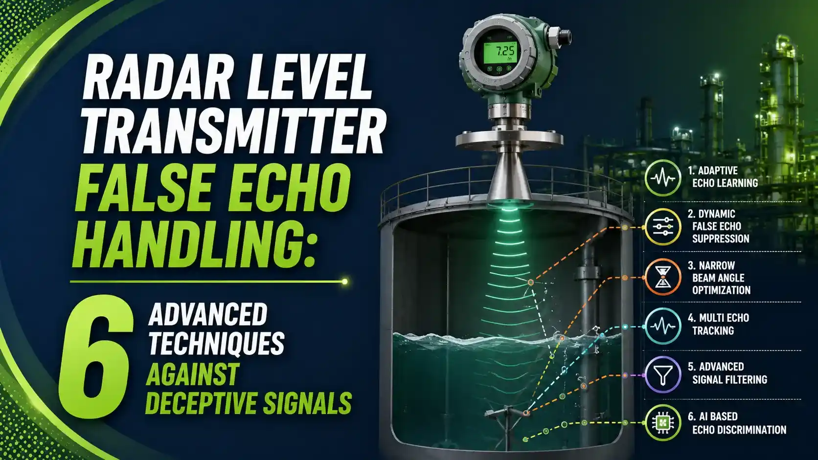
Agitator blades, heating coils, nozzles, ladders, and weld seams all reflect microwave energy exactly the way a liquid surface does. The transmitter has to decide which reflection matters, whether it's a non-contact radar or a guided wave probe style instrument.
This challenge sits on top of everything covered in automatic tank gauging generally, since false echo handling is really what separates a reliable radar installation from a noisy one.
The Physics: Fresnel Reflection at a Dielectric Boundary
Every radar echo starts with one equation. It comes straight from electromagnetic theory, not from any single vendor.
When a microwave crosses from air into a denser medium, part of its energy reflects. How much depends entirely on the change in dielectric constant, written as epsilon r.
Water, εr = 80: R = [(8.944-1)/(8.944+1)]^2 = 0.638 (63.8%, or -1.95 dB)
Gasoline, εr = 2: R = [(1.414-1)/(1.414+1)]^2 = 0.0294 (2.94%, or -15.3 dB)
This single formula explains why low dielectric hydrocarbons are so much harder to measure reliably than water or caustic solutions. A weak surface echo has far less margin over any false echo competing for attention. The same dielectric sensitivity is discussed further in Control.com's echo level measurement textbook chapter.
Echo Curve Anatomy: What T1 Through T4 Actually Mean
Guided wave and pulse radar transmitters plot amplitude against distance. Every peak on that curve gets tested against a named threshold, a process covered in more field detail in this guided wave radar diagnostics guide.
A null zone (UNZ) is not a threshold at all. It's a hold-off distance where every echo, real or false, gets ignored outright, regardless of amplitude.
6 Advanced Techniques for Handling False Echoes
Modern transmitters combine several distinct strategies. Each solves a different piece of the problem.
Static Tank Mapping
Records the empty-tank echo curve once, then permanently ignores echoes at those same fixed distances during operation, a technique described in depth in Roketboy's echo curve breakdown.
Amplitude Threshold Curve (ATC)
A threshold that varies with distance rather than a flat line, tightening or loosening sensitivity across the range.
Upper Null Zone (UNZ)
A hard hold-off distance near the reference point where no echo, regardless of strength, is ever considered valid.
Dielectric-Aware Amplitude Prediction
Uses the Fresnel formula to predict expected echo strength, flagging peaks that don't match the configured product.
Dynamic Behavioral Tracking
Ranks candidate echoes by how they move over time. A true surface tracks level changes; a false echo stays fixed.
Installation Geometry Optimization
Offsetting the antenna and maintaining clearance from obstacles reduces false echo strength before software ever gets involved.
Static Suppression vs Dynamic Tracking
Older transmitters relied almost entirely on a fixed map. Modern signal processing adds a behavioral layer on top.
Static Suppression (Tank Mapping)
Fast and simple, but blind to any obstruction that appears or shifts after the map was recorded, such as new buildup or agitator movement.
Dynamic Tracking (e.g. Smart Echo Supervision)
Evaluates every viable echo in real time against how a genuine surface actually behaves, adapting continuously to new conditions.
FMCW vs Pulse Radar: Different Math, Same Problem
Both radar types face identical false echo challenges, but they arrive at the echo curve through different processing paths. This is a similar tradeoff to the accuracy versus complexity discussion in flow measurement technology comparisons, where two methods solve the same problem differently.
| Aspect | Pulse Radar | FMCW Radar |
|---|---|---|
| Core measurement | Direct time-of-flight: d = c x t / 2 | Beat frequency between transmitted and received sweep |
| Dynamic range | Lower, more sensitive to weak surface returns | Higher, better separation of closely spaced echoes |
| Low dielectric performance | Requires higher transmit power or stilling well | Generally stronger performance without added hardware |
| False echo separation | Limited by pulse width resolution | Better resolution from wide frequency sweep bandwidth |
Common False Echo Sources and Root Fixes
Most false echo problems trace back to one of a small set of physical causes, much like the mechanical root causes covered in displacer level transmitter troubleshooting.
| Source | Why It Reflects | Primary Fix |
|---|---|---|
| Agitators, mixer blades | Metal surface, strong reflector, moving position | Dynamic tracking, not static mapping alone |
| Nozzles, tank wall proximity | Beam edge clips the nozzle or wall inside cone angle | Reposition antenna, offset ~1/2R from tank center |
| Heating coils, ladders | Fixed metal structure inside the beam path | Static tank mapping at commissioning |
| Foam or turbulence | Diffuse, weak, or unstable reflection | FMCW radar with wider dynamic range |
| Low dielectric product | Weak genuine echo per the Fresnel formula | Higher sensitivity radar, stilling well if needed |
Stilling Wells: A Mechanical Alternative to Software Suppression
Sometimes the simplest fix for false echoes isn't in the transmitter's menu at all. It's a piece of pipe.
A stilling well confines the radar beam inside a metal tube, physically blocking reflections from agitators, ladders, and structural obstructions before they ever reach the antenna.
The tradeoff is a parabolic or focused antenna requirement to manage reflections off the well's own inner wall, and periodic inspection for buildup inside the tube itself.
Do's and Don'ts of False Echo Configuration
✓ Do
- Record the empty-tank echo curve during commissioning, before startup
- Compare peak movement against a local gauge before assuming a fault
- Offset antenna position away from tank center and walls per vendor guidance
- Re-map after any internal modification, like a new agitator or coil
✗ Don't
- Lower the surface threshold blindly just to "catch" a weak echo
- Assume static tank mapping alone handles a moving agitator blade
- Mount the antenna aimed directly at a nozzle or support beam
- Ignore repeated false trips without reviewing the actual echo curve
Live Reflection Coefficient and Echo Strength Calculator
Enter a product's dielectric constant to calculate the theoretical Fresnel reflection factor and echo strength in decibels.
Reference Materials on Radar False Echo Handling
FAQs on Radar Level Transmitter False Echo Handling
External References
- Ultrasonic and Radar Echo Level Measurement, Control.com Textbook
- Guided-Wave Radar Instruments Diagnostics, Inst Tools
- Understanding the Echo Curve in Guided Wave Radar Transmitters, Roketboy
- How Does Smart Echo Supervision Work?, Emerson
- Understanding FMCW Radar Technology, Emerson
What we learn today
- False echoes are real, physically valid reflections, from agitators, nozzles, or coils, not random noise, and they follow the same Fresnel reflection physics as the surface echo itself.
- Echo curves are read against named thresholds: T1 (reference), T2 (surface), T3 (interface), and T4 (end of probe), plus a separate UNZ hold-off zone.
- Static tank mapping handles fixed obstructions well but misses anything that moves or changes after commissioning.
- Dynamic behavioral tracking, like Smart Echo Supervision, ranks echoes by how they move over time, distinguishing a true surface from a fixed false reflection automatically.
- Low dielectric products produce inherently weaker surface echoes, which is exactly why false echo handling matters most on hydrocarbons and other low-DK media.