
A K-factor is nothing more than a dividing factor, yet it is the single number standing between a raw pulse or milliamp signal and an accurate, trustworthy flow rate on your display.
Put simply, a flow meter generates a specific number of pulses for every unit of product passing through it. Detect those pulses reliably, and calculating flow rate and totals becomes a straightforward task.
The axial design of a turbine flow meter is inherently linear within a known turndown range, typically 15:1, based on the velocity of the measured fluid. The device generates a precise, repeatable K-factor based on the turning of its balanced rotor and the resulting frequency pulse signal from a magnetic coil assembly, delivering accuracy of plus or minus 0.15% with special calibration applied.
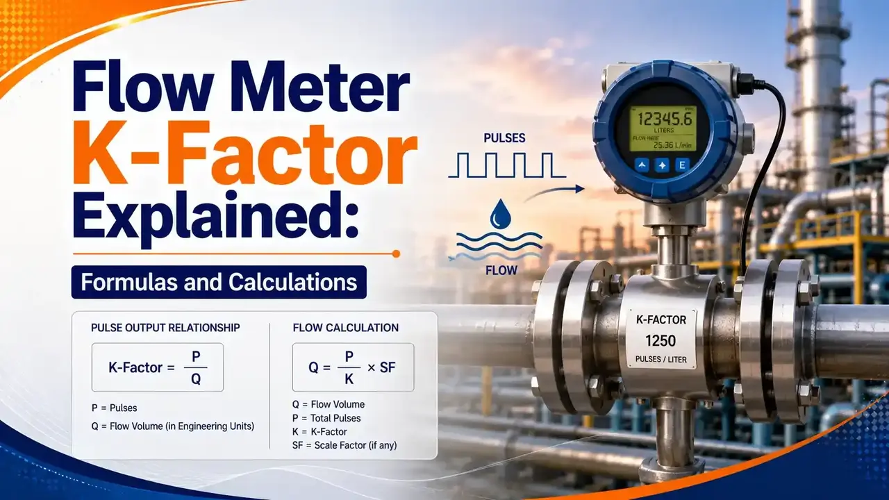
This guide covers what a K-factor actually is, how to calculate rate and totalizer K-factors from a pulse signal, how K-factors work for 4 to 20 mA analog signals, when multi point K-factors are needed for non linear or wide turndown applications, and how it all ties back to the broader flow measurement picture.
What Is a Flow Meter K-Factor?
Each pulse a flow meter generates represents a discrete amount of volumetric throughput, similar in spirit to how each division on an instrument scale represents a fixed unit of the quantity being read. Dividing the total number of pulses generated by the specific amount of liquid that passed through the meter determines the K-factor.
Every pulse output flow meter ships with a calibration certificate showing that the meter has been calibrated across its flow range, along with an average K-factor expressed as a number of pulses per unit volume, for example 200 pulses per U.S. gallon or 150 pulses per liter. That K-factor is the value entered into a batch meter, indicator, or totalizer to produce a readout in engineering units.
Mass flow can be derived by adding pressure and temperature sensors, factored electronically alongside the K-factor, similar to the compensation approach covered in our guide to temperature sensor installation. The electronic device continuously divides incoming pulses by the K-factor, or multiplies them by its inverse, to provide factored totalization, rate indication, and various outputs. This concept is applied widely across other meter types too, though those calculations carry more inherent error since they are derived from analog values rather than a precise mechanical pulse, unlike the direct pulse counting used in DP based flow measurement.
Calculating Rate and Totalizer K-Factors From a Pulse Signal
The frequency of the pulse output, the number of pulses per unit time, is directly proportional to the rotational rate of the turbine rotor, and therefore directly proportional to flow rate. Dividing the pulse rate by the K-factor gives the volumetric throughput per unit time.
Example: If a rate meter needs to display U.S. gallons per second, and the flow meter's K-factor is 210 pulses per U.S. gallon, the K-factor entered into the rate meter is simply 210. For gallons per minute instead, the rate K-factor becomes 210 ÷ 60 = 3.5.
For a totalizer set to totalize in whole gallons, the K-factor stays 210. To totalize in tenths of a gallon, the K-factor becomes 210 ÷ 10 = 21, since each pulse now needs to represent a smaller unit.
K-Factors for Analog Input Signals
When batching, indication, or totalization is carried out using an analog input signal, the flow meter first converts the 4 to 20 mA signal into a 0 to 10,000 Hz signal. The K-factor is then calculated by relating the engineering unit equivalent of 20 mA to that 10,000 Hz signal.
Example: A vortex meter outputs 20 mA at a flow of 2000 U.S. gallons per minute. The rate K-factor is 10,000 ÷ 2000 = 5. If the flow rate was given per minute, the totalizer K-factor for whole units is the rate K-factor multiplied by 60, giving 5 × 60 = 300 to totalize in gallons, or 5 × 60 ÷ 10 = 30 to totalize in tenths of a gallon.
For a flow rate given per second, multiply the rate K-factor by 1. For a flow rate given per hour, multiply by 3600, following the same logic used to relate any rate based unit to its corresponding totalized quantity.
🧮 Interactive Flow Meter K-Factor Calculator
Switch between pulse and analog based calculations to find your rate and totalizer K-factors.
Watch: Setting the K-Factor for Volumetric Flow and Total
This video walks through setting a real K-factor for both rate and totalized flow on an actual flow instrument.
Video: "Setting the K-factor for Volumetric Flow Rate and Total on the F-Series", via YouTube.
Multi Point K-Factor for Non Linear or Wide Turndown Applications
Some flow applications need more than a single K-factor. Two situations call for multiple K-factors: flow meters with non linear outputs, and wide turndown flow applications where a single average K-factor cannot represent the meter's behavior accurately across its full range, the same underlying concern covered in our guide to flow meter reading stability, and closely related to the sensitivity loss covered in orifice flowmeter rangeability.
Step 1: Calculate K-Factors per Range
Use the manufacturer's calibration sheet, or conduct on site tests against a calibrated standard, to calculate a K-factor for each flow range the meter will operate across.
Step 2: Relate Frequency to K-Factor
Map each incoming frequency, or flow value for analog inputs, range from the flow meter to its corresponding calculated K-factor.
Step 3: Program the Instrument
Enter these paired values, from 3 up to 16 points depending on the instrument, into the flow computer or indicator/totalizer.
A single K-factor assumes a meter behaves the same way at 10% of range as it does at 100%. Multi point K-factor exists precisely because that assumption breaks down for non linear meters and wide turndown applications, and pretending otherwise just hides the error rather than removing it.
A useful detail worth remembering when programming these points: the final point should use a flow or frequency value set well above the meter's true maximum, and if the last two calculated K-factors come out equal, any reading above that threshold is simply modified by the same final K-factor.
FAQs on Flow Meter K-Factor
You May Also Like
What Factors Affect the Stability of Flow Meter Readings?
A correctly calculated K-factor still depends on a stable, undisturbed pulse or analog signal reaching the instrument. This companion guide covers the 15 factors, from electrical interference to installation errors, that can destabilize any flow meter reading regardless of how well the K-factor itself is set.
Read Full Article →External References
What we learn today
- A K-factor is a dividing factor, typically expressed as pulses per unit volume, that converts a raw pulse or frequency signal into an engineering unit flow rate.
- Rate K-factor depends on the time basis of the display, while totalizer K-factor further depends on the desired totalizing precision.
- Analog K-factors relate a 4 to 20 mA signal, converted internally to 0 to 10,000 Hz, to the actual engineering unit flow rate at 20 mA.
- Multi point K-factor, using 3 to 16 programmed points, handles non linear meters and wide turndown applications a single K-factor cannot represent accurately.
- Turbine meters generate K-factor directly from a precise mechanical pulse, while other meter types derive an equivalent K-factor from less precise analog values.