
Flow Measurement · Thermal Dispersion · Mass Flow · Gas Flow · No Moving Parts
Thermal Mass Flow Meter Working Principle: 5 Proven Advantages for Gas Flow Measurement
A thermal mass flow meter measures gas flow by sensing how much heat is carried away by the moving gas : directly proportional to mass flow rate with no need for separate pressure or temperature compensation. This guide covers the complete working principle, the two sensing methods (constant temperature vs constant power), gas calibration, applications and a live flow calculator.
What Is a Thermal Mass Flow Meter and How Does It Work?
A thermal mass flow meter measures gas mass flow rate using a fundamental physics principle: a heated object loses heat faster when gas flows past it, and the rate of heat loss is directly related to the mass flow rate of that gas. Unlike orifice plates or venturi meters that infer flow from a pressure differential, thermal mass flow meters measure mass flow directly without needing separate density, pressure or temperature corrections.
The technology was first described mathematically by Louis Vessot King in 1914 (King's Law), originally developed for hot-wire anemometry in aerodynamics research. Industrial thermal mass flow meters adapted this principle for pipe and duct flow measurement, becoming the dominant technology for low-pressure gas flow, compressed air monitoring and natural gas custody applications where mass flow (not volumetric flow) is the parameter of real interest.
Because thermal mass flow meters output mass flow directly, they eliminate the need for the pressure and temperature compensation calculations required by volumetric meters such as orifice plates or vortex meters when gas density varies.
Thermal Mass Flow Meter Working Principle: 4 Steps
A heated RTD sensor element is maintained at a constant temperature above the gas temperature, typically 20-50°C higher.
→Moving gas carries heat away from the sensor by forced convection. More mass flow means more heat carried away per second.
→Electronics measure how much electrical power is needed to keep the sensor at constant temperature as the gas cools it.
→Power required is proportional to mass flow rate via King's Law. Transmitter outputs 4-20 mA proportional to mass flow directly.
Two Thermal Mass Flow Meter Sensing Methods: CTA vs CPA
The sensor is electrically heated and a feedback control loop continuously adjusts the power to keep the sensor at a fixed temperature differential above the gas. As flow increases, more power is needed to maintain the set temperature.
Measured signal: Electrical power (or current) required for constant temperature.
Best for: Fast response, wide dynamic range, most common industrial design.
A fixed amount of electrical power is continuously applied to the sensor. As gas flow increases, more heat is removed and the sensor temperature drops. The temperature difference (not power) is the measured variable.
Measured signal: Temperature difference between heated and reference sensor.
Best for: Simpler electronics, lower cost, slightly slower response than CTA.
King's Law: The Formula Behind Thermal Mass Flow Meter Working Principle
Where:
P = electrical power required to maintain sensor temperature (Watts)
A = heat loss constant at zero flow (conduction, radiation losses)
B = convective heat transfer constant (sensor geometry dependent)
m_dot = mass flow rate (kg/s or kg/h)
n = empirical exponent, typically 0.5 (King's original derivation)
Ts = sensor temperature (°C)
Tg = gas temperature (°C)
Rearranged to solve for mass flow rate (CTA method, fixed Ts-Tg): m_dot = [(P / (Ts - Tg)) - A] / B raised to power (1/n)
Key relationship: Power required increases with the SQUARE ROOT of mass flow rate Doubling mass flow does NOT double power needed : power increases by sqrt(2) = 1.41x This is why thermal mass flow meters have excellent low-flow sensitivity The constants A, B and exponent n are determined for each specific gas during factory calibration using a reference gas (often nitrogen or air). This is why thermal mass flow meters must be factory-calibrated for the SPECIFIC gas they will measure : a meter calibrated for air will read incorrectly on natural gas unless gas-specific correction factors are applied.
Thermal Mass Flow Meter Working
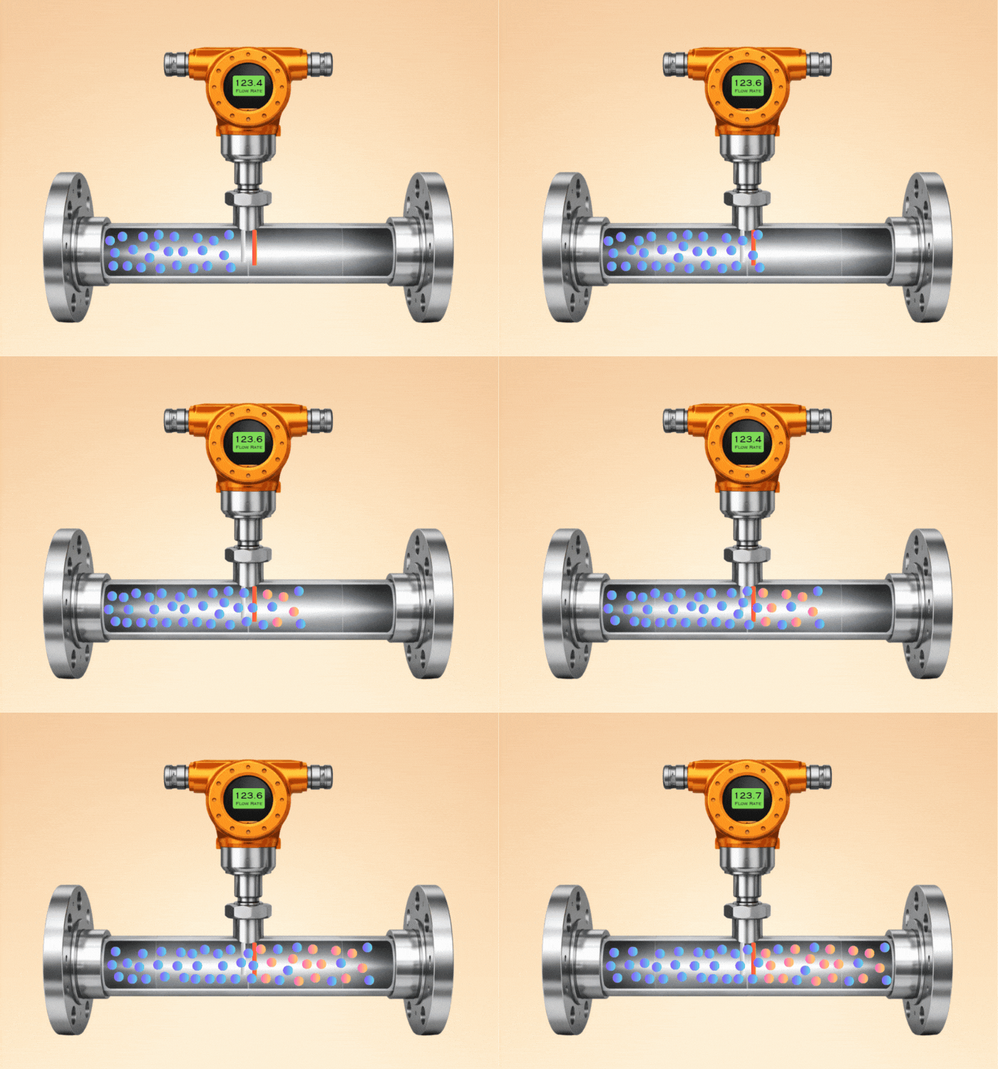
Probe contains 2 sensors (flow sensor and Temperature sensor). Flow sensor is self heated and Temperature sensor act as a reference sensor. Both sensors sit in the gas stream. One sensor measures true gas temperature continuously, allowing the electronics to compute the exact temperature differential (Ts - Tg) needed for King's Law regardless of ambient temperature changes.
Gas-Specific Calibration in Thermal Mass Flow Meter Working Principle
Industrial Applications of Thermal Mass Flow Meters
Energy audits, leak detection, and consumption tracking in plant compressed air systems. Most common thermal mass flow meter application.
Boilers, furnaces, burners. Precise air-to-fuel ratio control requires direct mass flow, not volumetric flow affected by temperature.
CEMS (Continuous Emissions Monitoring Systems) for flue gas flow rate, supporting environmental compliance reporting.
Wastewater treatment biogas measurement, landfill gas monitoring. Low-pressure applications where other meters struggle.
Ultra-low flow specialty gas delivery in chip fabrication. Micro thermal mass flow controllers for process gas dosing.
Building ventilation duct flow measurement, fume hood face velocity monitoring, laboratory air change rate verification.
5 Proven Advantages of Thermal Mass Flow Meters vs Key Limitations
- Direct mass flow output: No need for separate pressure or temperature compensation calculations that volumetric gas meters require.
- Excellent low-flow sensitivity: Works reliably at very low velocities (0.1-0.5 m/s) where vortex or orifice meters fail completely.
- Wide turndown ratio: Typically 100:1 or greater, far exceeding orifice plates (3:1) or even vortex meters (10:1).
- Low pressure drop: Insertion-style probes create minimal obstruction, unlike orifice plates which create significant permanent pressure loss.
- No moving parts: Solid-state RTD sensors with no rotating components, giving high reliability and low maintenance in clean gas service.
- Gas-specific calibration required: A meter calibrated for one gas reads incorrectly on a different gas without correction factors applied.
- Not suitable for liquids: Designed specifically for gas flow measurement. Liquid thermal dispersion meters exist but are a different technology category.
- Sensitive to gas composition changes: Variable gas mixtures (biogas, flare gas) cause measurement uncertainty unless the meter is configured for the expected composition range.
- Contamination affects accuracy: Dust, oil mist or condensation on the sensor changes its heat transfer characteristics and causes drift over time.
- Requires straight pipe runs: Like most flow meters, accuracy depends on a fully developed flow profile, typically 10-20D upstream straight pipe.
Thermal Mass Flow Meter vs Other Gas Flow Technologies
Thermal Mass Flow Meter Calculator
Enter the measured mass flow and pipe parameters to calculate volumetric flow and the equivalent 4-20 mA output for your transmitter range.
Quick FAQs: Thermal Mass Flow Meter Working Principle
- Coriolis Flow Meter: Direct Mass Flow Measurement for Liquids
- Turbine Flow Meter: Volumetric Flow Alternative for Clean Gas Service
- Reynolds Number: Why It Matters Less for Thermal Mass Flow Meters
- 4-20 mA Current Loop: How Thermal Mass Flow Transmitters Connect to DCS
- How to Calibrate Gas Flow Meters: Gas-Specific Calibration Methods
External References
- Fluid Components International: Thermal Mass Flow Meter Technology
- Endress+Hauser: Thermal Mass Flow Measurement Principle
- Sierra Instruments: How Thermal Mass Flow Meters Work
What we learn today
- A thermal mass flow meter heats a sensor above gas temperature and measures either the power needed to maintain that temperature (CTA) or the temperature drop at constant power (CPA). King's Law (P = (A + B x m_dot^n) x deltaT) governs this relationship, giving direct mass flow output with no pressure or temperature compensation needed.
- Gas-specific calibration is essential because different gases have different thermal conductivity and specific heat. A meter calibrated for air reads incorrectly on natural gas, hydrogen or biogas without applying gas-specific correction factors or a true gas-specific factory calibration.
- Five proven advantages: direct mass flow output, excellent low-flow sensitivity (0.1-0.5 m/s), wide turndown ratio (100:1+), low pressure drop, and no moving parts. Best applications: compressed air monitoring, combustion air control, biogas measurement and low-pressure gas flow where other technologies struggle with sensitivity or turndown.