
What is Signal Integrity? Causes, Problems, and Solutions Explained
Why a perfectly correct schematic can still fail on the bench, and what actually happens to a digital signal between the transmitter pin and the receiver pin.
Signal integrity ensures that electrical signals travel through a circuit without distortion or loss. Learn the causes of signal integrity problems, their effects, and practical solutions used in modern electronic and PCB design.
What is Signal Integrity?
Modern electronic systems are becoming faster, smaller, and more powerful. High-speed processors, FPGAs, memory devices, communication networks, and industrial controllers exchange enormous amounts of data every second. As signal frequencies continue to increase, maintaining signal integrity has become one of the biggest challenges in electronic design. Signal integrity, often shortened to SI, refers to the quality of an electrical signal as it travels from a transmitter to a receiver. A signal has good integrity when it reaches its destination without significant distortion, delay, or loss.
Poor PCB layout, long traces, impedance mismatch, crosstalk, reflections, and electromagnetic interference can distort a signal before it reaches the receiving device, causing communication errors, incorrect data, and unreliable system performance. This is no longer a concern only for advanced computer systems. It matters just as much in industrial automation, embedded systems, medical electronics, automotive controllers, communication equipment, and consumer electronics.
Real Life Example
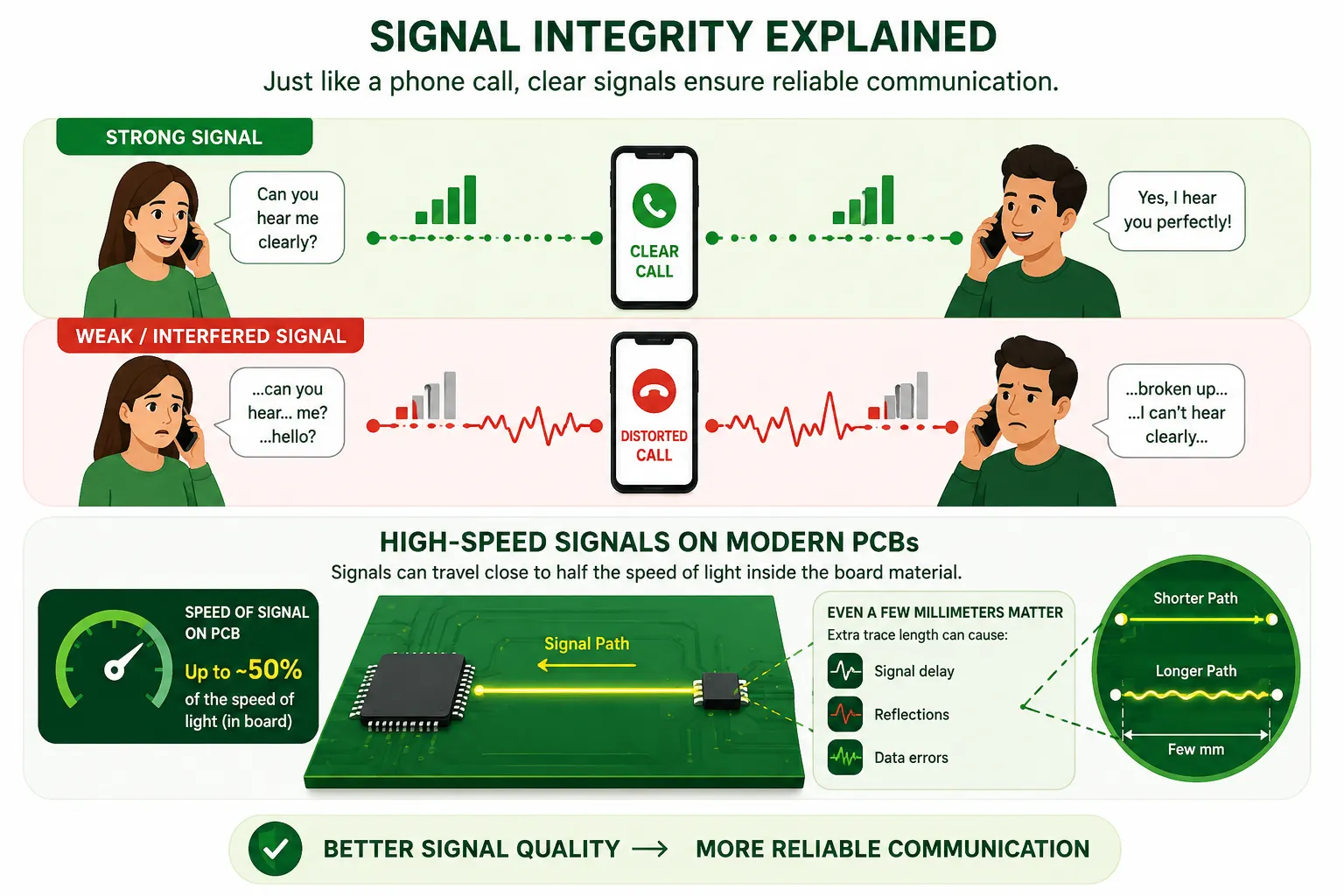
Imagine speaking to a friend over a mobile phone. If the network is strong, your voice reaches the other person clearly. If the signal is weak or affected by interference, your voice becomes distorted or breaks up. Electrical signals behave the same way. The better the signal quality, the more reliable the communication between electronic components.
Why is Signal Integrity Important?
Poor signal integrity can affect the performance of an entire electronic system. Maintaining it provides reliable data transmission, reduced communication errors, improved timing accuracy, better system stability, lower EMI, higher product reliability, and faster circuit performance. Whether you are designing a simple microcontroller board or a complex industrial controller, this should always be considered during the design stage, not fixed afterward.
4 Key Factors That Affect Signal Integrity
Trace Length
Long PCB traces add resistance, capacitance, and inductance, increasing delay and susceptibility to interference. Keep high-speed traces as short as possible.
Impedance Mismatch
When source, trace, and load impedances are not matched, part of the signal reflects back toward the source instead of reaching the receiver.
Crosstalk
Electromagnetic energy from one signal trace couples into a nearby trace. Closely spaced parallel traces make this worse.
Ground Plane Quality
A continuous ground plane gives current a low impedance return path. Broken or split planes force longer return paths and more noise.
6 Common Signal Integrity Problems and Solutions
Signal integrity problems become more noticeable as data rates and clock frequencies increase. Understanding each one helps engineers identify the root cause and apply the correct fix.
Signal Reflection
Crosstalk
Ringing
Overshoot and Undershoot
Ground Bounce
Timing Jitter
Eye Diagram: How Engineers Visualize Signal Integrity
An eye diagram is a graphical representation used to evaluate signal quality in high-speed digital communication. It is created by overlaying multiple digital waveforms on an oscilloscope, and the resulting pattern resembles a human eye. A wide open eye indicates excellent signal quality. A partially closed eye indicates poor performance.
- A wide, open eye means low noise, low jitter, and clean timing margins
- A closing or skewed eye signals rising noise, jitter, or signal reflections
Engineers use eye diagrams to evaluate noise, timing jitter, rise time, fall time, signal distortion, and bit error probability. They are commonly used for USB, Ethernet, PCI Express, HDMI, DDR memory, and serial communication.
Signal Integrity Analysis Before PCB Fabrication
Before manufacturing a PCB, engineers often perform this kind of analysis using simulation software to predict potential problems before the board is fabricated. Common analysis includes reflection analysis, crosstalk analysis, timing analysis, impedance analysis, and power integrity analysis. Popular simulation tools include Cadence Allegro, Altium Designer, Siemens HyperLynx, Keysight ADS, and Ansys SIwave. Performing this analysis early reduces costly PCB redesigns.
Comparison of Common Signal Integrity Problems
Practical Solutions for Improving Signal Integrity
- Use controlled impedance routing for critical signals
- Keep signal traces as short and direct as possible
- Maintain a continuous ground plane beneath high-speed traces
- Place decoupling capacitors near IC power pins
- Use proper termination to reduce reflections and ringing
- Separate analog and digital circuits
- Minimize crosstalk with adequate trace spacing
- Reduce the number of vias on high-speed signals
Signal Integrity vs Power Integrity: Key Differences
Many beginners confuse Signal Integrity with Power Integrity. Both are closely related, but they focus on different aspects of circuit performance. The former ensures signals travel correctly from transmitter to receiver, while Power Integrity ensures every component receives a stable and noise free power supply.
| Feature | Signal Integrity (SI) | Power Integrity (PI) |
|---|---|---|
| Purpose | Maintains signal quality | Maintains stable power supply |
| Primary Concern | Signal distortion | Voltage fluctuations |
| Affected By | Crosstalk, reflections, jitter | Power noise, voltage drop, ground bounce |
| Main Objective | Reliable data transmission | Reliable power delivery |
| Typical Solution | Controlled impedance, termination | Decoupling capacitors, power planes |
| Importance | Communication reliability | Circuit stability |
Both Signal Integrity and Power Integrity must be considered together when designing high-speed electronic systems.
Applications of Signal Integrity in Modern Electronics
High-Speed PCB Design
Computer motherboards, graphics cards, and communication equipment operating at high data rates.
Industrial Automation
PLCs, DCS systems, and SCADA networks rely on clean signal transmission for accurate data.
Computer Systems
Processors, DDR memory, PCIe, SATA, USB, and HDMI interfaces transfer data at gigabit speeds.
Automotive Electronics
ECUs connected through CAN, LIN, and Ethernet networks depend on reliable signal transmission.
Medical Equipment
ECG machines, MRI scanners, and patient monitors require accurate signal transmission for patient safety.
Aerospace and Defense
Navigation, radar, and satellite communication systems operate in electrically noisy environments.
Common Signal Integrity Mistakes to Avoid
✅ Do This
- Maintain controlled impedance throughout the signal path
- Keep high-speed traces short and direct
- Use a continuous ground plane under critical signals
- Place decoupling capacitors close to IC power pins
- Run signal integrity simulation before PCB fabrication
❌ Avoid This
- Routing high-speed traces over split ground planes
- Using long parallel traces that increase crosstalk
- Ignoring controlled impedance requirements
- Using excessive vias on high-speed signals
- Skipping signal integrity simulation during PCB design
What is Signal Integrity: Video Walkthrough
Frequently Asked Questions About Signal Integrity
- Wikipedia, Signal Integrity
- Altium, The Basics of Signal Integrity Analysis and Simulation in PCB Design
- Keysight, How to Analyze PCB Signal Integrity
- Sierra Circuits, Understanding Signal Integrity in PCBs
What We Learn Today
- Signal integrity is the ability of a signal to keep its correct voltage, timing, and waveform end to end
- Trace length, impedance mismatch, crosstalk, and ground plane quality are the four biggest factors affecting it
- Reflection, crosstalk, ringing, overshoot, ground bounce, and timing jitter are the six problems to watch for
- Eye diagrams give engineers a fast visual read on signal quality before problems reach production
- Good PCB layout, controlled impedance, and proper termination fix most signal integrity issues
- Signal integrity and power integrity are related but different, and both need attention in high-speed design