
Both the ultrasonic flow meter and the magnetic flow meter are non-intrusive, no-moving-parts technologies.
Both offer excellent accuracy, wide turndown, and low maintenance. The choice depends on seven factors that the two technologies handle very differently.
This guide covers the working principle of each type and all seven differences. See also the 4-20 mA signal guide for the output wiring used by both technologies.
The single most important difference: a magnetic flow meter only works with electrically conductive liquids.
An ultrasonic flow meter works with any liquid and most gases. If the fluid is a hydrocarbon, demineralised water, or a gas, only the ultrasonic meter is an option.
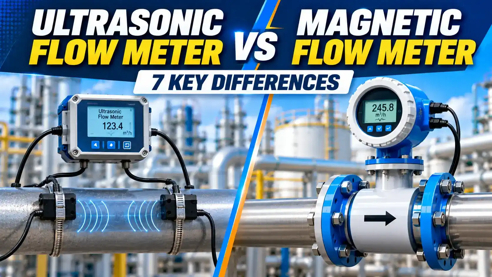
Working Principles: How Each Type Measures Flow
Magnetic Flow Meter (Magmeter)
A magnetic flow meter applies a magnetic field across the pipe using external coils.
When a conductive liquid flows through this field, it generates a voltage across two electrodes mounted in the pipe wall.
This voltage is proportional to the mean flow velocity: E = k × B × D × V (Faraday's law).
No moving parts touch the fluid. The meter is full-bore with no pressure loss.
A static DC field would cause electrochemical polarisation at the electrodes — a DC voltage building up on the electrode surface that would swamp the small flow-induced signal (typically a few millivolts).
By rapidly reversing the field direction and measuring the difference signal, the transmitter cancels the electrochemical DC offset while preserving the flow-velocity-proportional AC component. This technique was first patented by Foxboro in the 1950s and is still the basis of all modern magmeter designs.
Ultrasonic Flow Meter (Transit-Time)
A transit-time ultrasonic flow meter transmits ultrasonic pulses diagonally across the pipe in both directions simultaneously. Pulses travelling with the flow arrive slightly earlier than pulses travelling against it.
The transit-time difference (Δt) is proportional to mean flow velocity. The meter calculates V = (L / 2 cos θ) × (Δt / t_up × t_down).
The fluid must be acoustically transparent — clean enough for the beam to pass without scattering.
Doppler meters require particles or bubbles in the flow to reflect the ultrasonic beam. They cannot measure clean liquids at all — they need a minimum of about 100 ppm of suspended solids or entrained gas to function reliably.
Transit-time meters are the opposite: they work best in clean liquids and fail in dirty or aerated flows. This is why the term "ultrasonic flow meter" needs qualification — the performance characteristics of the two types are completely different.
7 Key Differences: Magnetic Flow Meter vs Ultrasonic Flow Meter
Difference 1: Fluid Conductivity Requirement
Magnetic flow meter: Requires the fluid to have electrical conductivity above approximately 5 to 20 µS/cm (depending on manufacturer). Suitable for water, wastewater, acids, caustic solutions, food fluids, and slurries.
Ultrasonic flow meter: No conductivity requirement. Suitable for hydrocarbons, demineralised water, ultrapure water, gases, steam, and any other fluid — including those where a magnetic flow meter cannot be used.
These applications require an ultrasonic flow meter or a Coriolis meter. A magmeter will give no signal or an unstable noisy reading on DI water.
Boiler feedwater after deaerating but before the boiler drum is a common example: conductivity can be as low as 0.1 µS/cm.
Difference 2: Gas and Steam Measurement
Magnetic flow meter: Cannot measure gases, steam, or non-conductive liquids. The Faraday induction principle requires a liquid conductor.
Ultrasonic flow meter: Can measure gases and steam. Multi-path ultrasonic meters are widely used on natural gas pipelines and steam headers. Clamp-on models can be retrofitted to gas lines without process shutdown.
A typical 5-path or 6-path ultrasonic meter achieves uncertainty below 0.5% over a 30:1 turndown — meeting the requirements of AGA Report No. 9 (American Gas Association).
This is the same technology used at LNG terminals to measure the enormous volumes of liquefied gas transferred between ships and storage tanks.
Difference 3: Clamp-On Installation
Magnetic flow meter: Always requires cutting the pipe and installing an inline flow body.
Cannot be installed without a process shutdown. Lining material must be specified at time of order.
Ultrasonic flow meter: The clamp-on variant attaches to the outside of the pipe with no cutting and no shutdown.
Ideal for temporary measurement, survey metering, and applications where a process shutdown is not permitted.
Errors in pipe wall thickness of even 1 mm can cause a 1 to 3% systematic flow error. Always measure pipe dimensions with an ultrasonic thickness gauge at the installation point rather than relying on nominal dimensions from a drawing.
Scale and deposits inside the pipe also increase the effective wall thickness and must be accounted for.
Difference 4: Dirty Fluid and Slurry Performance
Magnetic flow meter: Handles slurries, abrasive fluids, and heavily contaminated liquids well — provided conductivity is sufficient.
No acoustic beam to scatter. Electrode coating can cause gradual zero drift, addressed by self-cleaning DC pulse excitation.
Ultrasonic flow meter (transit-time): Requires a clear acoustic path.
Entrained gas, solids above 2 to 3% by volume, and heavy scaling scatter the beam and cause signal loss. Use Doppler ultrasonic or a magnetic flow meter for dirty service.
The symptom is a residual flow reading when the pump is off and valves are closed (called the "empty pipe" or "no-flow" error). A simple check: isolate the line completely and observe the reading. It should drop to zero within a few seconds of flow stopping.
If it does not, the electrodes need cleaning or the transmitter needs empty pipe detection calibration.
Difference 5: Pressure Loss
Magnetic flow meter: Zero permanent pressure loss. The full-bore flow body has the same internal diameter as the connecting pipe. No restrictions, no vena contracta, no turbulence-generating geometry.
Ultrasonic flow meter (inline): Also zero or near-zero permanent pressure loss. Clamp-on models have no pressure loss at all.
Both meter types are equivalent on this parameter. See the pressure drop calculation guide for context.
Difference 6: Bi-Directional Flow Measurement
Magnetic flow meter: Fully bi-directional by design. The induced voltage reverses polarity with the flow direction. A magnetic flow meter can measure forward and reverse flow simultaneously without any reconfiguration.
Ultrasonic flow meter: Also fully bi-directional. The transit-time difference reverses sign when flow reverses.
Both technologies are therefore suitable for pipeline pigs, surge monitoring, and batching applications with forward and reverse flow.
A magnetic flow meter in a district heating circuit measures both the supply and return flow in the same meter, using the sign of the voltage to determine direction.
Combined with a temperature measurement on both supply and return lines, the energy consumption of each building is calculated as: Energy = flow rate × density × specific heat × temperature difference.
Difference 7: Liner and Electrode Material Selection
Magnetic flow meter: Requires careful selection of liner material (rubber, PTFE, or ceramic) and electrode material (316 SS, Hastelloy, titanium, or platinum).
Wrong liner selection causes chemical attack, delamination, or vacuum collapse of the liner.
Ultrasonic flow meter: Clamp-on models have no wetted parts at all — no material compatibility issue.
For inline spool-piece models, only the pipe body and transducer seal material need specifying. Far simpler than a magmeter for aggressive fluids.
Vacuum can collapse a rubber liner inward, permanently distorting the flow bore and invalidating the calibration. Steam cleaning at temperatures above the liner rating (typically 80°C for soft rubber) causes liner swelling and delamination.
For steam-cleaned or vacuum lines, specify PTFE or ceramic lining. For temperatures above 180°C, specify ceramic lining only.
Side-by-Side: Magnetic vs Ultrasonic Flow Meter
| Parameter | Magnetic Flow Meter | Ultrasonic Flow Meter |
|---|---|---|
| Working principle | Faraday electromagnetic induction (E = k·B·D·V) | Transit-time difference or Doppler frequency shift |
| Fluid conductivity required | Yes: minimum 5 to 20 µS/cm | No: works on any fluid including non-conductive liquids and gases |
| Gas and steam measurement | No | Yes: multi-path designs for gas custody transfer |
| Clamp-on option | No: always inline, requires pipe cutting | Yes: clamp-on transducers, no shutdown required |
| Dirty fluid / slurry | Excellent: no beam path to scatter | Limited: solids above 2 to 3% volume scatter the acoustic beam |
| Permanent pressure loss | Zero (full bore) | Zero (full bore inline or clamp-on) |
| Bi-directional | Yes (polarity reversal) | Yes (transit-time sign reversal) |
| Wetted material specification | Liner and electrode material selection required | Clamp-on: none. Inline: pipe body and transducer seal only. |
| Accuracy (ideal conditions) | ±0.2 to ±0.5% of rate | ±0.5 to ±1% of rate (clamp-on: ±1 to ±3%) |
| Turndown ratio | Up to 100:1 | Up to 100:1 (transit-time); 10:1 (Doppler) |
| Typical applications | Water, wastewater, acids, caustic, food fluids, slurries, mining | Hydrocarbons, gas, steam, DI water, ultrapure water, cryogenic liquids, retrofit metering |
Flow Meter Technology Selector
Watch: Ultrasonic Clamp-On vs Electromagnetic Flow Meter
FAQ: Magnetic vs Ultrasonic Flow Meter
External References
- Magnetic Flow Meters: Selection and Application Guide | Emerson Rosemount
- Ultrasonic Flow Meters: Product Range and Selection | KROHNE (2025)
What We Learn Today
- The key selection rule: a magnetic flow meter requires electrical conductivity (minimum 5 to 20 µS/cm). An ultrasonic flow meter works on any fluid including gases, steam, hydrocarbons, and DI water.
- Clamp-on ultrasonic meters require no shutdown and no pipe cutting. Magnetic flow meters always require an inline installation with a process shutdown.
- Use a magnetic flow meter for slurries and dirty conductive liquids. Use a transit-time ultrasonic meter for clean liquids and all gas/steam applications.