
Swap a resistor for a capacitor and an op amp starts doing calculus, integrating or differentiating the input signal.
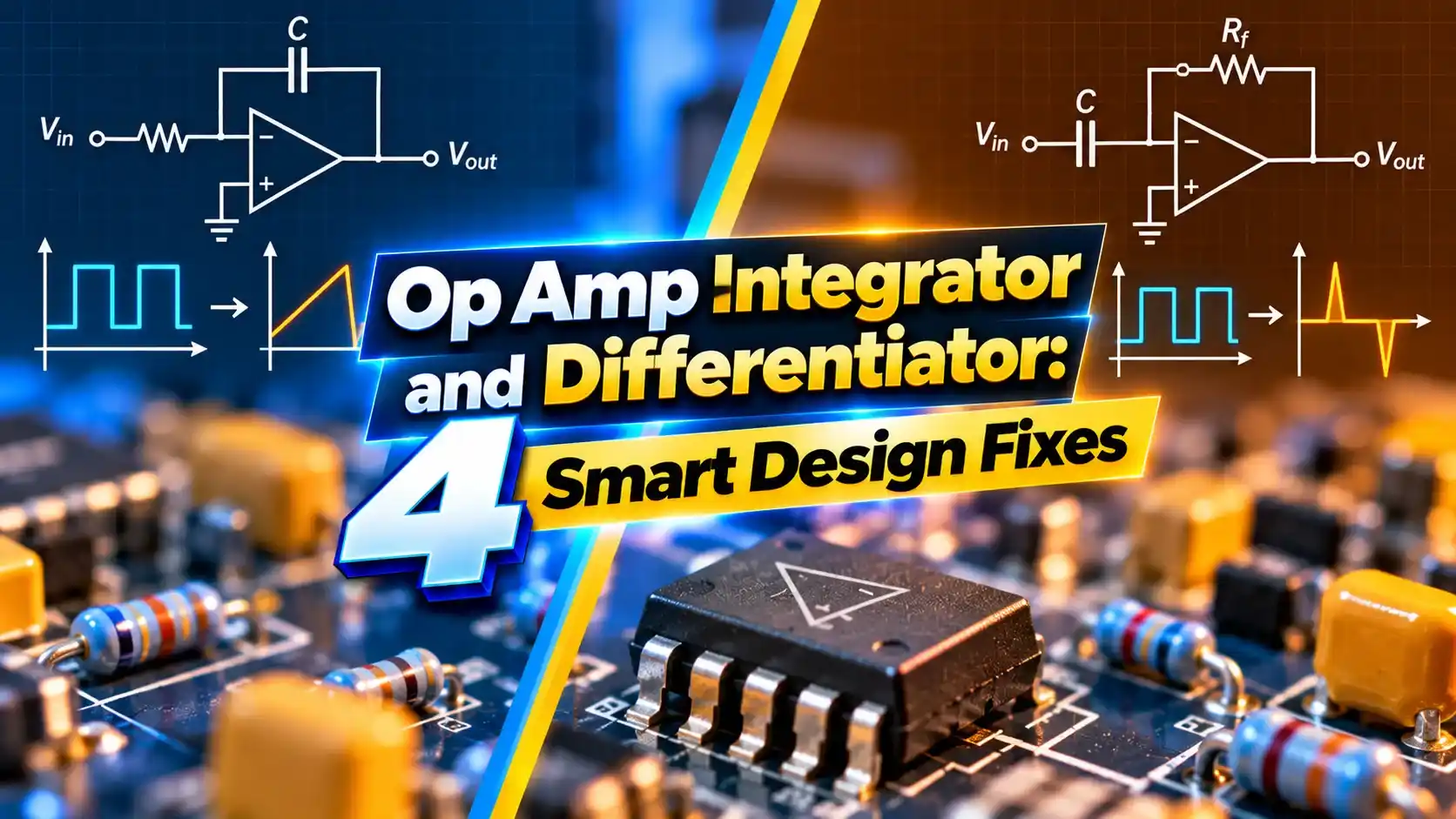
An op amp integrator produces an output proportional to the integral of its input, while a differentiator responds to the rate of change. Both use a resistor and capacitor around an inverting op amp.
What Is an Op Amp Integrator?
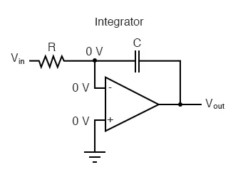
An op amp integrator is an inverting amplifier with a capacitor in the feedback path instead of a resistor. The output voltage is proportional to the integral of the input over time, built on the op amp basics of virtual ground.
The input resistor converts input voltage into a current, and that current charges the feedback capacitor. Because the inverting input stays at virtual ground, the capacitor voltage grows steadily as long as current flows.
A differentiator swaps the positions, with the capacitor at the input and the resistor in feedback. Its output depends on how fast the input changes.
Both circuits rely on capacitor charging behaviour explained in RC time constant basics.
Integrator and Differentiator Formulas
Differentiator: Vout = minus R × C × dVin ÷ dt
Integrator example, constant input:
Vin = 1 V, R = 10 kΩ, C = 1 µF, t = 5 ms
Change = 1 × 0.005 ÷ (10000 × 0.000001) = 0.5 V
Output ramps down by 0.5 V
Differentiator example:
Input ramp = 1 V per ms, R = 10 kΩ, C = 0.1 µF
Output = 10000 × 0.0000001 × 1000 = 1 V, inverted
The minus sign in both formulas comes from the inverting configuration. A positive input gives a falling output.
A square wave into an integrator becomes a triangle wave. A triangle wave into a differentiator becomes a square wave.
How the Integrator Output Builds Up
With any DC input or offset, the ideal integrator keeps ramping until it hits a rail. That is the biggest practical problem with the circuit.
Even the tiny input offset voltage of the op amp will slowly drive the output into saturation. The fixes below solve this.
4 Smart Design Fixes
Fix 1 turns the integrator into a low pass filter below a chosen corner frequency. It integrates correctly only above that corner, which is fine for AC signals.
Fixes 3 and 4 tame the differentiator, whose gain would otherwise rise without limit at high frequency. Zbotic notes that this rising gain amplifies noise and can cause oscillation.
Integrator vs Differentiator
| Feature | Integrator | Differentiator |
|---|---|---|
| Feedback element | Capacitor | Resistor |
| Input element | Resistor | Capacitor |
| Gain vs frequency | Falls with frequency | Rises with frequency |
| Noise behaviour | Smooths noise | Amplifies noise |
| Main risk | Drift to saturation | Instability and noise |
| Square wave in | Triangle out | Spikes out |
The integrator is naturally a low pass circuit and is far more common in practice. The differentiator is used carefully, usually with band limiting.
Compare these with passive networks in RC low pass and high pass filters, which behave similarly but without gain.
Where These Circuits Are Used
The integral term of a PID controller is exactly an integrator, removing steady state error over time.
Triangle waves from an integrator can drive a comparator to generate PWM, a common trick in motor drives and power supplies.
Choosing R and C Values
The unity gain frequency of an ideal integrator is 1 divided by 2π R C. For R of 10 kΩ and C of 10 nF, that is about 1.6 kHz.
Pick values so the integrator works well within the frequencies of interest. Use film or C0G capacitors for low leakage and stable value.
Select an op amp with low input bias current and offset, especially for slow integrators. A slow op amp adds phase error at higher frequencies.
Integrator Ramp Calculator
A negative input makes the output rise. Check that the final value stays inside the op amp output swing.
- Smooths noisy signals.
- Generates clean ramps.
- Core of analog control loops.
- Simple component count.
- Drifts with DC offset.
- Needs reset or DC feedback.
- Capacitor leakage causes error.
- Differentiator amplifies noise.
TI Integrator Circuit PDF
Integrator and Differentiator Video
Op Amp Integrator FAQ
Related Articles
- Op Amp Basics
- RC and RL Time Constant
- RC Low Pass and High Pass Filter
- Comparator Circuits Explained
- PID Controller Types Explained
External References
- Integrator Circuit, Texas Instruments
- Differentiator and Integrator Circuits, All About Circuits
- Integrator and Differentiator Circuits, Zbotic
- Op Amp Integrator, Wikipedia
What We Learn Today
- A capacitor in feedback makes the output the integral of the input.
- A differentiator responds to rate of change but amplifies noise.
- DC feedback, reset switches and band limiting make both circuits practical.