
A load cell gives only a few millivolts at full load, far too small for an ordinary microcontroller input. One low cost chip amplifies, digitises and filters that tiny bridge signal so a hobby board can weigh to a gram.
Kitchen scales, beehive monitors and small batching rigs all need to read a strain gauge bridge accurately. The HX711 does that job with a 24 bit converter, a built in amplifier and a simple two wire interface.

What Is the HX711?
The HX711 is a 24 bit analog to digital converter with a built in programmable gain amplifier, designed by Avia Semiconductor specially for weigh scales and industrial control that use bridge sensors. It connects directly to a load cell and sends readings to a microcontroller over two digital pins.
A load cell is a metal body with bonded strain gauges arranged as a full Wheatstone bridge. At rated load it typically outputs only 1 to 3 mV for every volt of excitation, so a 5 V supply gives a few millivolts at most.
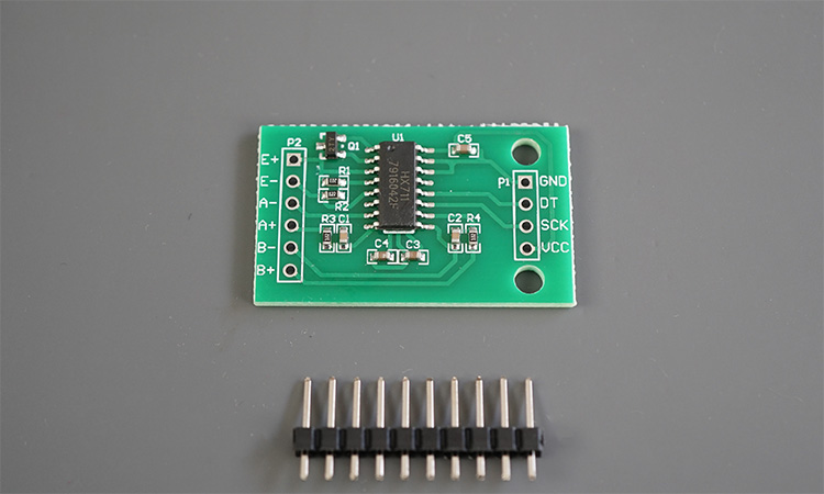
The HX711 amplifies that small differential signal, converts it with high resolution and outputs a signed 24 bit number. The microcontroller then subtracts an HX711 zero offset and divides by a calibration factor to get grams or kilograms.
A full scale input of 20 mV spread over 24 bits gives a step of only about 2.4 nV. In practice noise, not resolution, sets how finely an HX711 scale can really weigh.
HX711 Key Specifications
According to the HX711 datasheet, channel A offers a gain of 128 or 64 and channel B has a fixed gain of 32. With a 5 V analog supply, the full scale differential input is ±20 mV at gain 128, ±40 mV at gain 64 and ±80 mV on channel B.
All supplies work from 2.6 V to 5.5 V, normal current is below 1.5 mA and power down current is below 1 µA. The output rate is 10 SPS or 80 SPS with the internal oscillator, chosen by the RATE pin.
| Setting | Channel | Full Scale at 5 V | PD_SCK Pulses |
|---|---|---|---|
| Gain 128 | A | ±20 mV | 25 |
| Gain 32 | B | ±80 mV | 26 |
| Gain 64 | A | ±40 mV | 27 |
Inside the HX711, the front end works like an instrumentation amplifier feeding a sigma delta converter. The datasheet quotes input noise of 50 nV rms at gain 128 and 10 SPS, rising to 90 nV rms at 80 SPS.
Use gain 128 on channel A for almost every load cell, since a 1 mV/V cell at 5 V uses only part of the ±20 mV range. Keep channel B for a second sensor or a supply check.
How the HX711 Talks to a Microcontroller
The HX711 uses two pins, DOUT and PD_SCK, in a simple serial format that looks like SPI but is not a standard bus, unlike the protocols in SPI vs I2C. When a new HX711 conversion is ready, DOUT goes low.
The datasheet states that 25 pulses select channel A at gain 128, 26 select channel B at gain 32 and 27 select channel A at gain 64. Any microcontroller with two free GPIO pins can read the HX711, from an Arduino Uno to an ESP32.
Keep each PD_SCK high pulse short, because holding the clock high for longer than 60 µs puts the HX711 into power down mode. An interrupt arriving in the middle of a read can cause exactly this fault on busy boards.
Wiring a Load Cell to the HX711
The four wires of a load cell form the two diagonals of a Wheatstone bridge. One pair carries HX711 excitation and the other pair carries the output signal.
| Load Cell Wire | Bridge Function | HX711 Pin |
|---|---|---|
| Red | Excitation positive | E+ |
| Black | Excitation negative | E minus |
| White | Signal negative | A minus |
| Green | Signal positive | A+ |
This colour code follows the Random Nerd Tutorials guide and suits most bar type cells sold in India, but some makers use other colours. If the reading falls when you add weight, simply swap A+ and A minus or invert the sign in software.
Bathroom scale cells with three wires are half bridges, so four of them are combined into one full bridge before reaching the HX711. The difference between bonded designs is covered in bonded and unbonded strain gauges.
Random Nerd Tutorials reports a raw reading of minus 141449 for a 300 g test weight, giving a calibration factor of about minus 471.5. The negative sign only means the signal wires were connected in reverse polarity.
Bridge Output and Counts Formula
Before calibrating, it helps to predict the raw HX711 count change for a given load. The bridge output is the sensitivity times the excitation times the fraction of rated load applied.
Full scale FS = 0.5 × AVDD ÷ Gain
Counts = V ÷ FS × 2^23
Example:
5 kg cell, S = 1 mV/V, Vexc = 5 V, Load = 2 kg, Gain 128
V = 1 × 5 × 2 ÷ 5 = 2.000 mV
FS = 2500 ÷ 128 = 19.53 mV
Counts = 2 ÷ 19.53 × 8388608 = 858993 counts
Factor = 858993 ÷ 2000 g = 429.50 counts per g
This theoretical factor gets you close, but real cells differ from their nominal sensitivity, so always finish with a known weight. Many modules also excite the bridge from an onboard regulator below 5 V, which changes the numbers proportionally.
HX711 Load Cell Counts Calculator
6 Simple Steps to Set Up and Calibrate
Random Nerd Tutorials describes the same idea: tare with the platform empty, place an object of known weight and divide the reading by that weight to get the calibration factor. Weight then equals the HX711 reading minus offset, divided by the factor.
Use a reference mass close to the working range, for example 1 kg on a 5 kg cell, and repeat at two or three loads to confirm linearity. The wider topic of errors and confidence is covered in measurement uncertainty in calibration.
Second Worked Example: Tare and Weight
Suppose the empty platform gives an HX711 reading of 84200 counts and a 1000 g reference mass reads 513700 counts. The calibration factor is (513700 minus 84200) ÷ 1000 = 429.5 counts per gram.
An unknown parcel then gives an HX711 reading of 342000 counts. Its weight is (342000 minus 84200) ÷ 429.5 = 600.2 g, which the display would round to 600 g.
Store the calibration factor in EEPROM or flash, but tare again at every power up. The zero point drifts with temperature and mounting stress far more than the span does.
Reducing Noise and Drift in HX711 Scales
The datasheet noise figure of 50 nV rms is only about 0.001 percent of a 5 mV bridge signal, so most real world noise comes from wiring, power and mechanics. Run the cell cable as shielded twisted pair and keep it away from motor and relay wiring.
Decouple the supply pins with 100 nF close to the chip, as explained in how decoupling capacitors work, and avoid powering the HX711 from a noisy USB port. Average several HX711 readings in software, or use a moving average or median filter.
Temperature changes shift both zero and span, the effect described in zero and span shift. Let the scale warm up for a few minutes and keep the cell away from direct sun or hot electronics.
- Use 10 SPS unless the application truly needs speed.
- Twist and shield the four load cell wires.
- Join the shield to ground at the amplifier end only.
- Mount the amplifier board close to the load cell.
- Fit 100 nF decoupling and a clean supply.
- Average 10 or more readings for static weighing.
- Mount the cell on spacers so it can flex freely.
- Add a mechanical overload stop to protect the cell.
The HX711 datasheet lists simultaneous rejection of 50 Hz and 60 Hz supply interference among its features. That is useful in India, where mains hum at 50 Hz couples easily into long load cell cables.
- Very low cost and widely available modules.
- 24 bit resolution with built in amplifier.
- Only two microcontroller pins needed.
- Low power with a sleep mode below 1 µA.
- Maximum 80 SPS, too slow for dynamic weighing.
- Non standard serial timing is sensitive to interrupts.
- No legal for trade approval on its own.
- Module quality and excitation level vary widely.
Where the HX711 Is Used
For continuous industrial weighing, such as a weigh feeder, engineers use certified weighing indicators with higher speed and approvals. The HX711 remains an excellent tool for learning, prototypes and non trade applications.
HX711 Datasheet PDF
Load Cell Calibration Video
HX711 FAQ
The HX711 is a 24 bit converter with a built in amplifier, designed for load cells and other bridge sensors. It turns a few millivolts of bridge output into a digital number.
Makers and engineers use it in digital scales, force rigs and weight monitoring systems. A microcontroller reads the HX711 through just two pins, called data and clock, using simple code.
Use gain 128 on channel A for nearly all load cells, because it gives a full scale of about 20 millivolts at 5 volts. That range suits typical 1 to 3 millivolt per volt cells well.
Gain 64 doubles the input range on the same channel for larger signals. Channel B has a fixed gain of 32 and suits a second sensor.
First tare the empty platform and store that reading as the zero offset. Then place a known weight and record the new raw reading.
Divide the HX711 reading minus the offset by the known weight to get the calibration factor for your cell. Every later weight equals the reading minus offset, divided by that factor.
A negative HX711 reading usually means the signal wires A+ and A minus are swapped. It can also happen when the cell is mounted so that load bends it the opposite way.
Swap the two signal wires or simply use a negative calibration factor in code. Both fixes give the same correct weight on the display.
Use 10 samples per second for static weighing, since noise is lower and mains hum is rejected better. The datasheet shows noise of 50 nanovolts at 10 and 90 at 80 samples per second.
Choose 80 samples per second only when you must follow fast changes. Many cheap HX711 modules tie the rate pin low, so check the board first.
Drift usually comes from temperature change, mechanical creep or a stressed mounting. A noisy power supply and long unshielded wires add more random variation.
Let the scale warm up, tare at every start and keep the cell away from heat sources. Use shielded twisted wiring and a clean, well decoupled supply for the HX711 board.
The HX711 chip alone is not approved for legal metrology, and a trade scale needs a certified complete instrument from an approved maker. In India such scales must meet Legal Metrology rules.
The HX711 is ideal for learning, prototypes and process indication where approval is not required. For billing or trade, buy a verified and stamped weighing system.
Related Articles
- Load Cell Working Principle
- Strain Gauge Working Principle
- Wheatstone Bridge Applications
- Instrumentation Amplifier Working
- Weigh Feeder Working Principle
External References
- HX711 24 Bit ADC for Weigh Scales Datasheet, Avia Semiconductor
- ESP32 with Load Cell and HX711 Amplifier, Random Nerd Tutorials
- Load Cell, Wikipedia
What We Learn Today
- The HX711 is a 24 bit ADC with gains of 128, 64 and 32, giving a full scale of about 20 mV at gain 128 with 5 V.
- A four wire load cell connects as a Wheatstone bridge to E+, E minus, A+ and A minus, and the microcontroller reads data on two pins.
- Calibrate by taring empty, applying a known weight and dividing reading minus offset by that weight, then use 10 SPS and shielding to cut noise.