
Every digital meter, lift indicator and counter panel still relies on a few simple LED bars arranged in the shape of the number eight. Learn how they are wired, how to light any digit and how to drive them safely from a decoder or Arduino.
A 7 segment display shows the digits 0 to 9 by switching seven LED bars on and off. This guide covers its pin diagram, both common types, the hex code truth table, decoder ICs, resistor sizing and multiplexing.
What Is a 7 Segment Display?
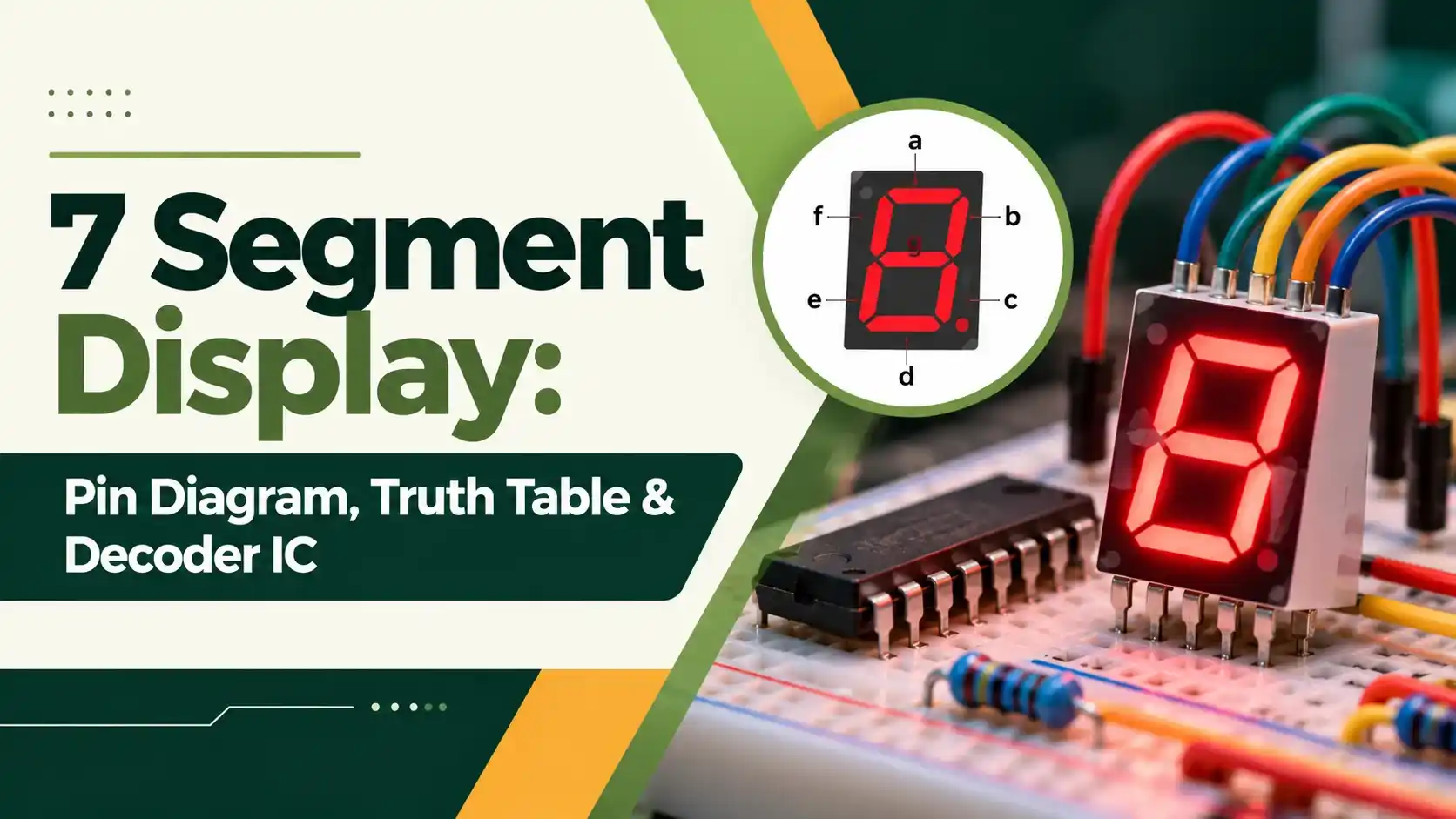
A 7 segment display is a numeric indicator made of seven LED bars, named a to g, arranged so that lighting different combinations forms the digits 0 to 9. An eighth LED, the decimal point, is usually added, and all segments share one common pin that is either the anode or the cathode of the LEDs.
- Seven LED segments a to g plus a decimal point, in a 10 pin package.
- Pins 3 and 8 are usually the common pin.
- Common cathode: common to ground, segment driven high to glow.
- Common anode: common to plus 5 V, segment pulled low to glow.
- Each segment needs its own current limiting resistor, typically 220 Ω at 5 V.
Segment a is the top bar, the letters run clockwise through b to f, and g is the middle bar. Lighting all seven gives the digit 8.

7 Segment Display Pin Diagram
Last Minute Engineers notes that a single digit has 10 pins: eight segment pins for a to g plus DP, and two common pins, usually pins 3 and 8.
| Pin | Function | Pin | Function |
|---|---|---|---|
| 1 | Segment e | 6 | Segment b |
| 2 | Segment d | 7 | Segment a |
| 3 | Common | 8 | Common |
| 4 | Segment c | 9 | Segment f |
| 5 | Decimal point | 10 | Segment g |
This pinout is the one used by the very common 0.56 inch single digit parts such as the 5161AS common cathode and 5161BS common anode modules. Always confirm the pinout in the datasheet of your exact part.
To find the type, set a multimeter to diode test and put the red probe on pin 3 and the black probe on pin 7. If segment a glows faintly, it is common anode; if not, reverse the probes, and a glow then means common cathode.
Common Anode vs Common Cathode
All LED cathodes are joined to the common pin, which goes to ground. A segment lights when its pin is driven high through a resistor.
All LED anodes are joined to the common pin, which goes to plus 5 V. A segment lights when its pin is pulled low through a resistor.
Last Minute Engineers points out that both types look almost identical from outside and describes common anode as the more popular type. Choose the one that suits your driver, since swapping types later means inverting every code or changing the decoder, as in any decoder based design.
A 7 segment display can also show letters such as A, b, C, d, E and F, which is how hexadecimal values are displayed. Letters like K, M, W and X cannot be formed clearly with seven bars, so alphanumeric displays use 14 or 16 segments instead.
7 Segment Display Truth Table With Hex Codes
The truth table below lists which segments light for each digit. The hex code assumes bit 0 is segment a and bit 6 is segment g, with the decimal point off, which is the usual order in microcontroller code.
| Digit | Segments ON | g f e d c b a | CC Hex | CA Hex |
|---|---|---|---|---|
| 0 | a b c d e f | 0 1 1 1 1 1 1 | 0x3F | 0xC0 |
| 1 | b c | 0 0 0 0 1 1 0 | 0x06 | 0xF9 |
| 2 | a b d e g | 1 0 1 1 0 1 1 | 0x5B | 0xA4 |
| 3 | a b c d g | 1 0 0 1 1 1 1 | 0x4F | 0xB0 |
| 4 | b c f g | 1 1 0 0 1 1 0 | 0x66 | 0x99 |
| 5 | a c d f g | 1 1 0 1 1 0 1 | 0x6D | 0x92 |
| 6 | a c d e f g | 1 1 1 1 1 0 1 | 0x7D | 0x82 |
| 7 | a b c | 0 0 0 0 1 1 1 | 0x07 | 0xF8 |
| 8 | a b c d e f g | 1 1 1 1 1 1 1 | 0x7F | 0x80 |
| 9 | a b c d f g | 1 1 0 1 1 1 1 | 0x6F | 0x90 |
For common anode, every bit is inverted and the decimal point bit 7 is set to 1 to keep it off, giving 0xC0 for zero. The inputs are usually BCD numbers from 0000 to 1001, and each segment output can be simplified with a Karnaugh map if you build the decoder from gates.
BCD to 7 Segment Decoder ICs
A decoder IC converts a 4 bit BCD input into the seven segment outputs, so a counter or controller needs only four lines per digit. Texas Instruments describes the CD4511B as a CMOS BCD to 7 segment latch decoder driver whose bipolar outputs can source up to 25 mA, enough to drive common cathode LEDs directly through resistors.
TI lists three useful control inputs on the CD4511B: Lamp Test to light every segment, Blanking to switch the digit off or modulate brightness, and Latch Enable to store the BCD code. It also blanks the outputs for BCD inputs above 1001, so invalid codes show nothing.
| Feature | CD4511 | 74LS47 |
|---|---|---|
| Logic family | CMOS 4000 series | TTL, low power Schottky |
| Display type | Common cathode | Common anode |
| Output stage | Sources current, active high | Open collector, active low |
| Supply | Rated at 5, 10 and 15 V | 5 V |
| Extra inputs | Lamp test, blanking, latch | Lamp test, ripple blanking |
The 74LS47 belongs to the TTL family and pulls its outputs low to light a common anode digit. Its ripple blanking inputs and outputs let you suppress leading zeros, so a four digit counter shows 25 instead of 0025.
Current Limiting Resistor Calculation
Each segment is an LED, so it needs a series resistor just like a single indicator LED. Last Minute Engineers uses about 2 V drop and 15 mA for a typical red segment, which gives 200 Ω at 5 V, rounded up to the standard 220 Ω value from the E12 resistor series.
Vs = 5 V, Vf = 2 V, If = 15 mA
R = (5 minus 2) ÷ 0.015 = 200 Ω
Next E12 value = 220 Ω
Actual If = 3 ÷ 220 = 13.6 mA
P = If² × R = 40.9 mW, so a 0.25 W part is fine
Digit 8: 7 × 13.6 = 95.5 mA on the common pin
Multiplexing a 4 Digit 7 Segment Display
A four digit module shares the eight segment lines across all digits and gives each digit its own common pin. The controller lights one digit at a time and moves to the next quickly, so persistence of vision makes all four appear steady, a form of multiplexing.
Because each digit is on for only a quarter of the time, it looks dimmer, so designers raise the peak segment current within the LED pulse rating. The common pin can then carry close to 100 mA, so drive it through a transistor rather than straight from a microcontroller pin.
The ATmega328P on an Arduino Uno has an absolute maximum of 40 mA per I/O pin. A common pin carrying 95 mA for the digit 8 would exceed it, which is why multiplexed displays always use transistor drivers.
To save pins further, the segment data can be shifted out serially with a 74HC595 shift register.
Arduino 7 Segment Display Example
For a common cathode digit, store the codes in an array such as byte d[10] = {0x3F,0x06,0x5B,0x4F,0x66,0x6D,0x7D,0x07,0x7F,0x6F}; and write each bit to the pin that drives segments a to g. For common anode, either use the inverted codes or invert each bit before writing it.
Last Minute Engineers wires segments a to g to Arduino pins 3, 2, 8, 7, 6, 4 and 5, with DP on pin 9, and uses the SevSeg library by Dean Reading. The library handles the refresh loop through setNumber() and refreshDisplay().
If your 7 segment display shows strange shapes instead of digits, check the pin mapping first. A single swapped wire between segments b and f is the most common cause on breadboards.
Troubleshooting a 7 Segment Display
| Symptom | Likely Cause | Fix |
|---|---|---|
| Nothing lights | Wrong display type or common pin open | Check CA or CC and the common wiring |
| All segments always on | Codes inverted for the type | Use the inverted hex table |
| One segment dead | Open segment or wiring fault | Test that LED in diode mode |
| Ghost digits when multiplexing | No blanking between digits | Turn all commons off before loading new data |
| Flicker | Refresh too slow | Increase the scan rate |
| Dim display | Resistor too large or low duty cycle | Recalculate the resistor and peak current |
Myths About Seven Segment Displays
Where Seven Segment Displays Are Used
In industry, the 7 segment display is common on loop powered indicators, temperature controllers and digital counters. Its high brightness and wide viewing angle still beat many small LCDs in a dusty plant.
- Bright and readable from a distance.
- Simple to drive with a decoder or a few pins.
- Low cost and widely available.
- Works over a wide temperature range.
- Shows digits and only a few letters.
- Draws more current than an LCD.
- Needs many pins without multiplexing.
- Multiplexing adds firmware and flicker risks.
CD4511B Decoder Datasheet PDF
Video on Seven Segment Display Hex Codes
7 Segment Display FAQ
It contains seven LED bars arranged in a figure eight, plus a decimal point. Lighting a chosen group of bars forms each digit from 0 to 9.
All LEDs share one common pin, which is either the anode or the cathode. A decoder IC or microcontroller switches the individual segment pins to show the required number.
In a common anode part, all LED anodes join at the common pin, which goes to the positive supply. Segments light when their pins are pulled low.
In a common cathode part, all cathodes join at the common pin, which goes to ground. Segments light when their pins are driven high, so the codes are inverted.
Set the multimeter to diode test and touch the red probe to a common pin and the black probe to a segment pin. If the segment glows, the part is common anode.
If nothing lights, swap the probes and try again. A glow with the black probe on the common pin means it is common cathode.
A single digit 7 segment display usually has 10 pins. Eight of them drive segments a to g and the decimal point, and two are common pins.
The two common pins, normally pins 3 and 8, are joined inside the package. Four digit modules usually have 12 pins because the segment lines are shared between digits.
The CD4511 is the usual choice for common cathode digits, and the 74LS47 suits common anode digits. Both convert a 4 bit BCD input into seven segment outputs.
The CD4511 adds a latch and blanks invalid codes above 1001. Many microcontroller projects skip the decoder completely and use a simple lookup table of hex codes in firmware instead.
Calculate it from the supply voltage minus the segment forward voltage, divided by the desired current. At 5 V with about 2 V drop and 15 mA, the result is 200 ohms.
Round up to the next standard value, which is 220 ohms. Use one resistor for every segment so that each digit shows even brightness whatever number is lit.
Flicker appears when the refresh loop is too slow or is interrupted by other code such as delays. Each digit must be refreshed often enough that the eye cannot see it switching.
Avoid long delay calls in the main loop, or use a timer interrupt for the refresh. Blank all digits before loading new segment data to stop ghosting.
Related Articles
- BCD Binary Coded Decimal Explained
- Encoder vs Decoder in Digital Logic
- LED Working Principle
- 74HC595 Shift Register
- Digital Logic Gates Explained
External References
- CD4511B BCD to 7 Segment Latch Decoder Driver Datasheet, Texas Instruments
- How Seven Segment Display Works and Interface It with Arduino, Last Minute Engineers
- Seven Segment Display, Wikipedia
What We Learn Today
- A 7 segment display has seven LED bars a to g plus a decimal point, usually in a 10 pin package with two common pins.
- Common cathode digits need high segment signals and suit the CD4511, while common anode digits need low signals and suit the 74LS47.
- Use one resistor per segment, about 220 Ω at 5 V, and drive multiplexed common pins through transistors, never straight from a microcontroller pin.
