
Three wires from a microcontroller can drive dozens of LEDs or relays, thanks to one small serial to parallel chip.
The 74HC595 shift register receives data one bit at a time and presents it on eight parallel outputs. Its built in latch lets all outputs change together, and chips can be chained for more outputs.
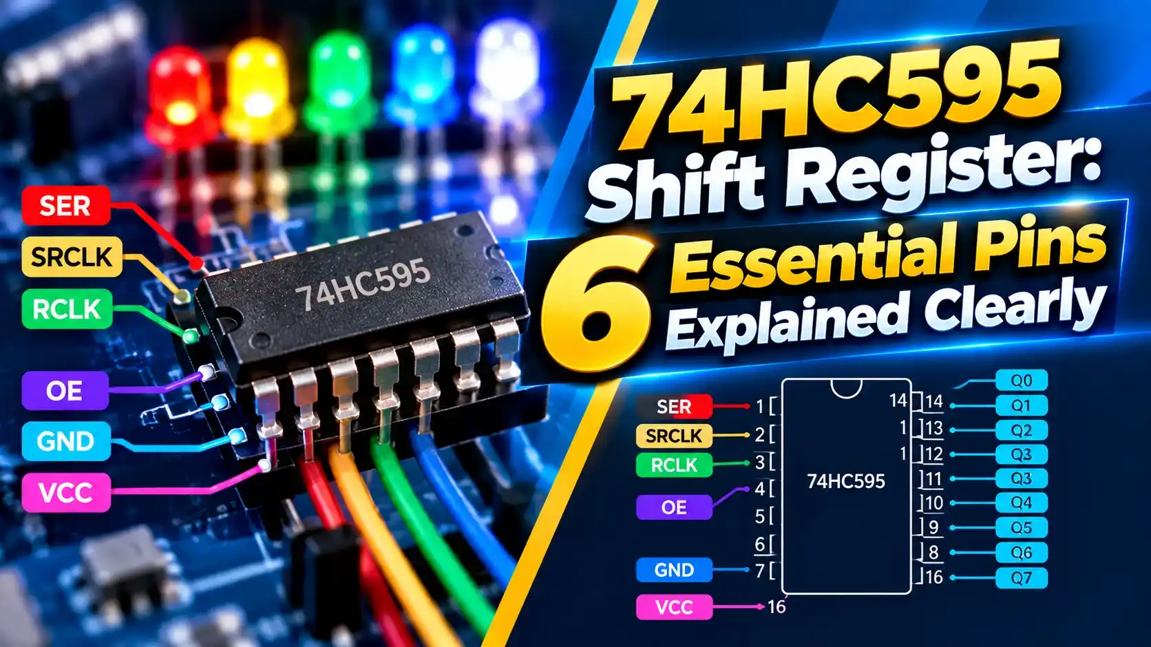
What Is the 74HC595 Shift Register?
The 74HC595 shift register is an 8 bit serial in, parallel out logic IC with a separate storage register and three state outputs. It is built from the same flip flops described in flip flop types.
Data enters one bit per clock pulse, shifting along an internal chain of eight stages. A second clock then copies the whole byte into an output latch in one step.

Because the outputs update only when the latch clock arrives, LEDs or relays never show half shifted patterns. That is the key advantage over simpler shift registers.
The idea is the same as the software shift instructions in PLC shift registers, but done in hardware at very high speed.
6 Essential Pins and Their Jobs
In many simple projects, OE is tied to ground and SRCLR to the supply, leaving just SER, SRCLK and RCLK. That is how three microcontroller pins control eight outputs.
Driving OE with PWM dims all outputs together, a handy trick for LED displays. Pulling SRCLR low clears the internal register, but outputs change only after the next latch pulse.
How Data Moves Through the Chip
This is a classic sequential circuit, where each clock edge moves the state forward. The first bit sent ends up on QH, and the last bit sent sits on QA.
On Arduino, the shiftOut function handles the clock and data sequence. Other controllers use SPI hardware, which is a natural fit for this kind of serial communication.
Update Time and Current Formula
Update time ≈ Bits ÷ Clock frequency
Total current = Outputs on × Current per output
Worked example:
3 chained chips = 24 outputs
Clock = 1 MHz, update time ≈ 24 µs plus latch pulse
8 LEDs on one chip at 10 mA each = 80 mA
80 mA exceeds the 70 mA package limit, so use 5 mA LEDs or drivers
The TI datasheet gives an absolute maximum of about 35 mA per output and 70 mA through the supply or ground pin. Designing near those numbers shortens chip life.
For relays, motors or bright LEDs, add transistor or MOSFET drivers on each output. Our LED working principle guide shows how to pick series resistors.
Daisy Chaining the 74HC595 Shift Register
Connect QH prime of the first chip to SER of the second and share SRCLK and RCLK between all chips. Now 16 bits must be clocked in before the latch pulse.
Each added chip gives eight more outputs without using extra microcontroller pins. Long chains simply take a little longer to update.
Keep clock lines short and add a decoupling capacitor near every chip. Noisy clocks cause random bits to shift, which shows up as flickering outputs.
74HC595 vs Other Output Expanders
| Option | Interface | Outputs | Best For |
|---|---|---|---|
| 74HC595 | 3 wire serial | 8 per chip, chainable | LEDs, displays, simple outputs |
| I2C expander | 2 wire I2C | 8 or 16 | Shared bus, fewer wires |
| Decoder IC | Parallel address | One active output | Selecting one line at a time |
| LED driver IC | Serial | 16 or more with current control | Large LED matrices |
A decoder activates just one output at a time, as explained in encoder vs decoder. The shift register can turn on any combination.
For inputs, the matching part is a parallel in, serial out register such as the 74HC165.
Typical 74HC595 Shift Register Uses
Pairing a microcontroller with these chips is one of the first expansion tricks students learn.
For industrial outputs, use proper driver ICs or relay modules with isolation rather than driving loads directly.
Chain and Current Calculator
Reduce LED current or add drivers until the result stays within the limit. Check the exact values in your supplier datasheet.
- Many outputs from three pins.
- Latched, glitch free updates.
- Easy daisy chaining.
- Low cost and widely available.
- Limited output current.
- Serial update adds small delay.
- No built in current control for LEDs.
- Needs drivers for heavy loads.
SN74HC595 Datasheet PDF
Shift Register Explained Video
74HC595 Shift Register FAQ
Related Articles
- Flip Flop Types
- Sequential Circuits Explained
- Ripple vs Synchronous Counters
- Latches in Digital Logic
- PLC Shift Register Instructions
External References
- SN74HC595 Datasheet, Texas Instruments
- Shift Register Tutorial, Last Minute Engineers
- ShiftOut Tutorial, Arduino
- Shift Register, Wikipedia
What We Learn Today
- Serial bits shift in on SRCLK and appear together on the outputs after RCLK.
- Chaining chips adds eight outputs each without extra controller pins.
- Respect the per pin and total current limits or add drivers.