
A control valve is only as good as the actuator that moves it, because an undersized actuator cannot close tightly and an oversized one wastes air and money. Adding up the real forces on the plug and stem gives a confident, reliable choice every time.
Every control valve needs enough force to stroke against process pressure, overcome packing friction and press the plug firmly into its seat. Actuator sizing turns these forces into a clear thrust or torque figure with a sensible margin.
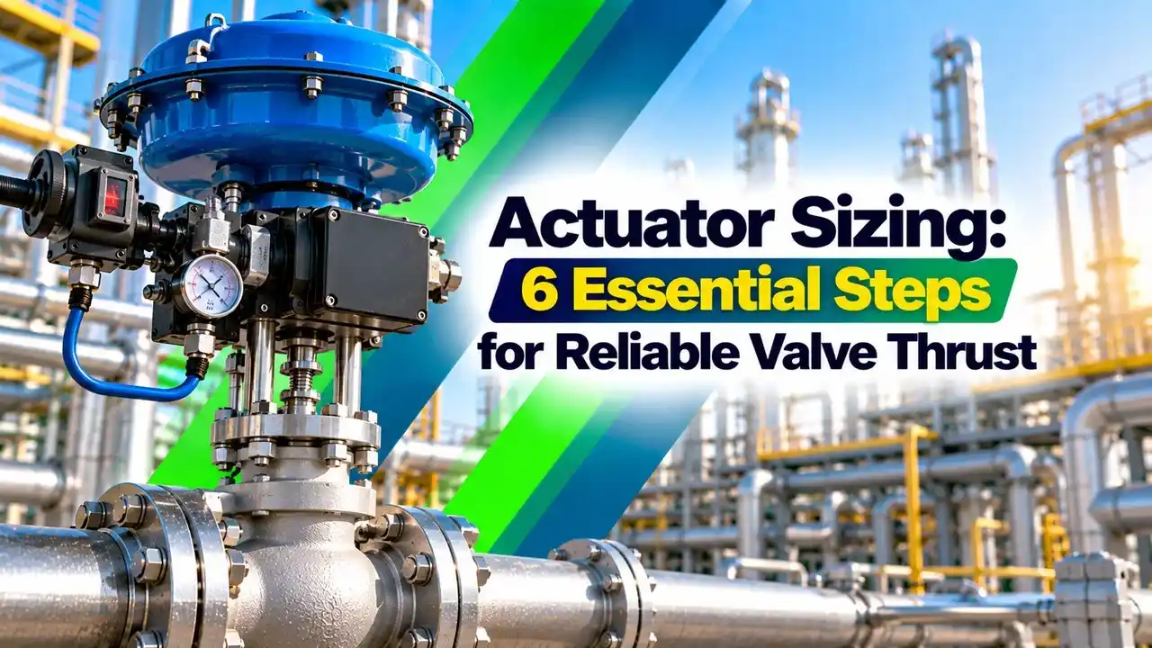
What Is Actuator Sizing?
Actuator sizing is the process of calculating the thrust or torque a control valve needs and then choosing an actuator that delivers it, with margin, at the minimum available supply pressure. It applies to the diaphragm, piston and electric types described in valve actuator types and applications.

For a sliding stem globe valve the answer is a thrust in newtons or pounds force, while for ball and butterfly valves it is a torque in newton metres. Both start from the internal parts of the valve, shown in basic parts of a control valve.
Valve World Americas sums up the force balance neatly. The available thrust equals the air pressure multiplied by the effective diaphragm area, minus the opposing spring force.
Forces That Act on a Sliding Stem Valve
Three main forces decide linear actuator sizing: the unbalance force from process pressure, the seat load needed for shutoff and the friction of the stem packing. The way these act depends on how sliding stem valves work and on the flow direction through the plug.
Process pressure acting on the unbalanced area of the plug and stem.
Extra force that presses the plug into the seat ring for shutoff.
Resistance of the stem packing rings to stem movement.
Seal friction, bellows, piston ring and spring forces in special trims.
Processing Magazine gives a striking example from a 2 inch Fisher ET valve at 200 psig. With balanced trim the unbalanced area is only 0.27 square inches and the force is 54 lbf, but with unbalanced trim the same valve sees about 840 lbf.
Balanced trims use a cage and a sealed plug with pressure balancing holes, so process pressure acts on both sides of the plug. That is why a large balanced valve can often use a much smaller actuator than an unbalanced one.
Seat Load and Shutoff Class
In actuator sizing, seat load is expressed as force per unit length of the seat circumference, so it scales with the port diameter. The required value rises with the leakage class defined in ANSI/FCI 70.2, explained in control valve seat leakage classes.
Processing Magazine uses 40 lbf per linear inch for Class IV metal seats on a port of 2.3125 inches. The circumference is π × 2.3125 = 7.26 inches, so the seat load is 7.26 × 40 = 290.6 lbf.
In SI units, 40 lbf per inch equals about 7 newtons per millimetre of seat circumference. Higher classes such as Class V need much more load, and soft seats need far less, so always take the figure from the valve maker for the trim chosen.
Never add seat load to a throttling only valve that has no shutoff requirement. It inflates the actuator sizing result and pushes you toward a larger, slower actuator than the duty needs.
Packing Friction in Actuator Sizing
The Valtek sizing manual from Flowserve lists packing friction from about 44 lbf for small stems with PTFE rings up to about 2193 lbf for 3 inch stems with heavy duty packing. Stem size and packing material therefore matter as much as pressure.
Plant Engineering notes that new packing has the highest friction, which may fall to about 50 percent after break in, so actuator sizing must use the new packing value. PTFE suits service up to about 232 °C, while flexible graphite works up to about 816 °C but brings higher friction, as discussed in control valve troubleshooting.
6 Essential Actuator Sizing Steps
Step one includes the fail action, because a fail close valve relies on the spring for seating while a fail open valve relies on air. Choose that action first, as explained in fail open, fail closed and fail locked positions.
Thrust Formula and Worked Example
Seat load = seat load per mm × π × d
Required thrust = (unbalance + seat load + packing) × safety factor
Example: port d = 50 mm, shutoff ΔP = 10 bar, unbalanced plug
Area = π × 0.05² ÷ 4 = 0.001963 m²
Unbalance = 10 × 100000 × 0.001963 = 1963.5 N
Seat load = 7 N/mm × π × 50 = 1099.6 N
Packing = 220 N
Sum = 3283.1 N
Required thrust = 3283.1 × 1.25 = 4103.9 N, about 4.10 kN
Linear Actuator Thrust Calculator
Enter zero seat load for a throttling valve without a shutoff duty, and use the balanced area instead of the full port area for a balanced trim. The calculator then shows how strongly trim choice changes the actuator sizing result.
Spring Range and Supply Pressure in Actuator Sizing
A spring and diaphragm actuator has a spring range, the air pressure that starts and completes the stroke on the bench with no process load. The effective diaphragm area converts every bar of air into force, so the same area and spring decide both directions.
Air to close thrust = effective area × (supply minus upper bench set)
Effective area = 450 cm² = 0.045 m², bench set 0.4 to 1.2 bar, supply 2.5 bar
Fail close seating force = 0.045 × 0.4 × 100000 = 1800 N
Fail open seating force = 0.045 × (2.5 minus 1.2) × 100000 = 5850 N
This actuator sizing check compares these numbers with the 3283 N needed before margin in the earlier example. The fail open version with 5850 N passes easily, while the fail close version with only 1800 N of spring force cannot seat the plug and needs a stiffer spring or a larger actuator.
Spirax Sarco shows the same effect on a PN5400 actuator with a DN50 valve. Changing from a 0.2 to 1.0 bar spring to a 1.0 to 2.0 bar spring raises the maximum allowable differential pressure from 3.0 bar to 13.3 bar, which needs a valve positioner to supply the higher signal.
Spirax Sarco notes that 0.2 to 1.0 bar is the most widely used pneumatic control signal for actuators. Many modern valves use stiffer springs and a positioner fed from a 4 to 6 bar instrument air supply instead.
Always size with the lowest instrument air pressure the plant can guarantee, not the normal header pressure. Wet or dirty air also reduces reliability, so keep an eye on instrument air dew point.
Rotary Valve Actuator Sizing by Torque
Ball and butterfly valves need torque instead of thrust, and the torque changes through the stroke. The highest values usually occur at breakaway from the closed seat and, for butterfly valves, at the dynamic torque peak in mid travel.
Rack and pinion actuators give a nearly constant torque, while scotch yoke actuators give high torque at both ends of travel, which suits seated valves. For rotary actuator sizing, the trade off is compared in scotch yoke vs rack and pinion actuator.
Diaphragm vs Piston Actuator Choice
| Feature | Spring Diaphragm | Spring Return Piston | Double Acting Piston |
|---|---|---|---|
| Typical supply | Up to about 4 bar | Up to about 10 bar | Up to about 10 bar |
| Fail safe action | Built in spring | Built in spring | Needs volume tank or lock |
| Best use | Throttling globe valves | High thrust compact duty | Large on off and long stroke |
Diaphragm actuators give smooth throttling and simple fail safe action, while pistons deliver more thrust from a smaller body at higher supply pressure. A detailed comparison is in diaphragm actuator vs piston actuator.
Commissioning and Verification Checklist
- Bench set matches the datasheet before mounting on the valve.
- Full stroke is achieved at minimum supply pressure.
- Valve closes tightly against maximum shutoff ΔP.
- Stroke time meets the process or safety requirement.
- Packing is adjusted to the maker torque, not overtightened.
- Positioner calibration and travel feedback are confirmed.
- Signature or step test results are stored for future comparison.
For shutdown valves, record the stroke and breakaway data during partial stroke testing, since rising friction over the years shows up there first. The same data supports emergency shutdown system proof tests.
Common Actuator Sizing Mistakes
- Tight shutoff at the worst process condition.
- Smooth throttling with less overshoot.
- Reliable fail safe action on loss of air.
- Lower air use and smaller accessories.
- Packing friction varies with wear and adjustment.
- Process data for worst cases is often uncertain.
- Vendor seat load figures differ between makers.
- Large margins increase cost and stroke time.
Valtek Linear Actuator Sizing Manual PDF
Actuator Sizing Video Tutorial
Actuator Sizing FAQ
It is the calculation of the thrust or torque that a valve needs under its worst operating condition. The engineer then selects an actuator that delivers that value with margin.
The calculation includes unbalance force, seat load and packing friction for linear valves. Rotary valves use breakaway, running and dynamic torque values from the valve maker.
Use the maximum shutoff pressure drop that the valve can see, not the normal operating drop. This is often the pump dead head pressure or the relief valve set pressure.
Using normal pressure drop is one of the most common sizing errors. The valve may then stroke well in service but fail to close during an upset.
Multiply the seat load per unit length by the circumference of the seat or port. Processing Magazine uses 40 lbf per linear inch for a Class IV metal seat example.
A port of 2.3125 inches therefore needs about 290.6 lbf of seat load. Higher leakage classes need more load, so confirm the value with the valve maker for that trim.
Packing friction opposes every stem movement and adds directly to the required thrust. Graphite packing usually has much higher friction than PTFE packing at the same stem size.
Plant Engineering notes that new packing has the highest friction, which may halve after break in. Size the actuator with the new packing value for a safe result.
Bench set is the air pressure range that strokes the actuator fully with no process forces acting on the valve. A typical example is 0.4 to 1.2 bar on a spring and diaphragm unit.
The lower end decides the spring seating force on a fail close valve. The upper end decides how much air remains for seating on a fail open valve.
Take the breakaway, running and end torques from the valve maker at the maximum shutoff pressure. Then compare them with the actuator torque curve at the minimum supply pressure.
Scotch yoke actuators give high torque at both ends of travel. Rack and pinion actuators give nearly constant torque, which suits valves with flatter torque curves.
Use the margin stated in your project specification or recommended by the valve maker. Many actuator sizing procedures add a margin of about 25 percent over the calculated thrust or torque.
Very large margins are not better, because they slow the stroke and increase air use. They can also overload stems and seats during closing on small valves.
Related Articles
- Diaphragm Actuator vs Piston Actuator
- Scotch Yoke vs Rack and Pinion Actuator
- Valve Actuator Types and Applications
- Control Valve Seat Leakage Classes
- Valve Torque and Actuator Failure
External References
- Linear Actuator Sizing, Valtek Sizing and Selection Manual, Flowserve
- Size Control Valve Actuators to Overcome the Force, Processing Magazine
- Valve Actuator, Wikipedia
What We Learn Today
- Actuator sizing adds unbalance force, seat load and packing friction at the maximum shutoff pressure drop, then applies a design margin to find the thrust.
- Seat load scales with port circumference, and Processing Magazine uses 40 lbf per linear inch for a Class IV metal seated valve example.
- Check spring bench set and minimum air supply, because a fail close valve relies only on spring force to seat the plug tightly.