
A sensor cell, a microcontroller and a transistor output have replaced the spring and microswitch in many hydraulic, pneumatic and process skids. Set up correctly, this compact device gives a precise switch point, a live display and full diagnostics over IO Link.
Modern machines and skids rely on solid state switches that measure pressure electronically and switch a transistor output. This guide covers how they work, how to wire PNP and NPN outputs, and how to set switch points, windows and IO Link parameters.
What Is an Electronic Pressure Switch?
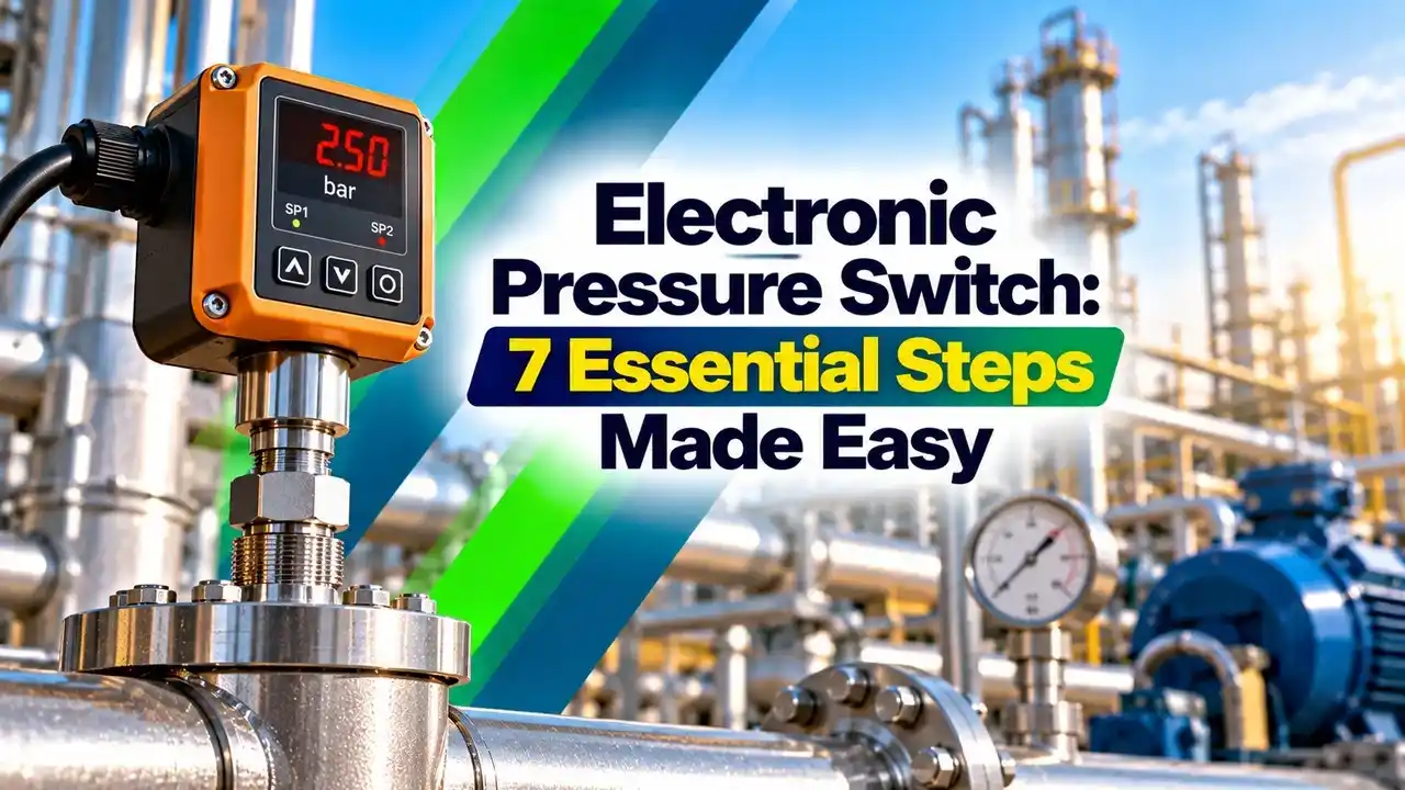
An electronic pressure switch is a device that measures pressure with a sensor cell, compares it with user set limits in a microcontroller and switches a transistor output when a limit is crossed. It does the same job as a mechanical pressure switch, but with digital precision and no moving contact.
The sensing cell is usually a piezoresistive silicon die or a thin film strain gauge on a stainless steel diaphragm, as explained in piezoresistive vs capacitive pressure sensors. Most models add a 4 digit display, push buttons and often an analog output as well.
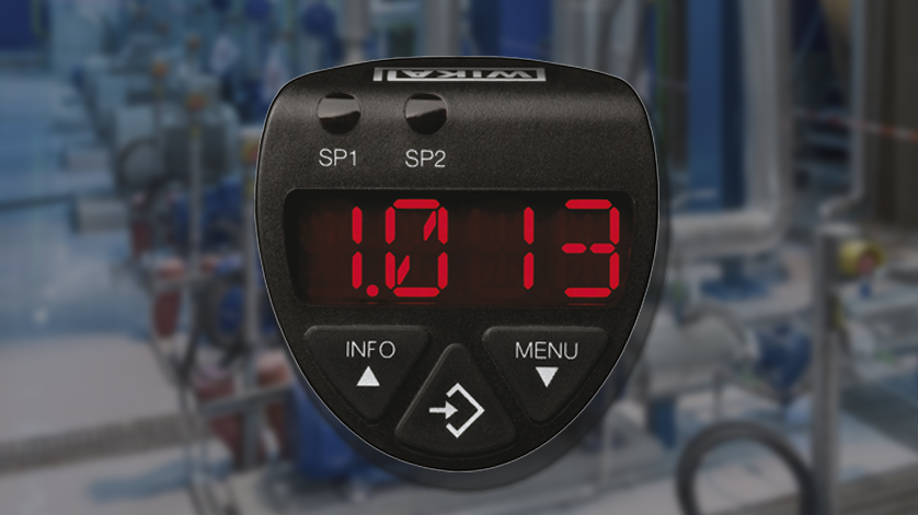
Because the switch point of an electronic pressure switch is a number in memory, it can be read on the display, changed with buttons, copied to a spare unit or downloaded from the PLC. That is the main reason machine builders have moved away from screw adjusted switches.
Inside the Device: From Pressure to Output
WIKA specifies its PSD 4 electronic pressure switch with a maximum measured error of 0.5 percent of span per IEC 61298 2 and a long term drift of 0.1 percent of span. It also states a service life of 100 million switching cycles, which no mechanical contact can match.
The same electronics can also drive a scaled 4 to 20 mA or 0 to 10 V signal, so one device can serve as both a switch and a transmitter. The overview of pressure signal outputs explains how these choices compare.
JUMO notes that mechanical pressure switches usually have a fixed hysteresis of about 10 to 20 percent of the switch point. An electronic unit lets you set it freely within the measuring range.
Electronic vs Mechanical Pressure Switch
| Feature | Mechanical | Electronic |
|---|---|---|
| Sensing | Bourdon, diaphragm or piston | Sensor cell and microcontroller |
| Output | Dry contact, AC or DC | PNP or NPN transistor, often analog |
| Hysteresis | Fixed or limited | Freely adjustable |
| Display | None | Live pressure value |
| Power | Not needed | 24 V DC supply |
| Diagnostics | None | Fault codes and IO Link data |
A mechanical switch still wins where no power is available or where the contact must switch mains AC directly. For a broader view, see electronic vs mechanical pressure sensors and the role of deadband in pressure switches.
PNP and NPN Switching Outputs
Transistor connects the load to plus 24 V, and the load returns to 0 V.
Transistor connects the load to 0 V, and the load is fed from plus 24 V.
4 to 20 mA or 0 to 10 V proportional to pressure.
A PNP output sources current, so it pairs with a sinking PLC input, as explained in sinking and sourcing in PLC. The rule is exactly the same as for proximity sensors described in NPN and PNP proximity sensors.
WIKA rates each PSD 4 output at 250 mA, and the factory setting is PNP with either PNP or NPN selectable in the menu. That is enough for a PLC input or a small relay coil, but not for a solenoid valve or contactor.
Check the PNP or NPN setting before you power the PLC card. A wrong selection gives no damage in most cases, but the input simply never turns on and wastes commissioning time.
Hysteresis and Window Switching Modes
In hysteresis mode, the output of an electronic pressure switch turns on at the switch point SP and resets only when pressure falls below the lower reset point RP. JUMO explains that a correct hysteresis prevents the system from oscillating, for example a pump that would otherwise start and stop many times a minute.
In window mode, the output stays active only while pressure is inside a band between a high limit FH and a low limit FL. JUMO describes the window function as monitoring whether pressure stays between lower and upper limits, which suits filter and process checks.
Hysteresis, percent of span = (SP minus RP) ÷ span × 100
Example:
Range 0 to 10 bar, SP = 6.0 bar, RP = 5.4 bar
Hysteresis = 6.0 minus 5.4 = 0.6 bar
Percent of span = 0.6 ÷ 10 × 100 = 6.0 percent
WIKA gives a minimum hysteresis of 0.25 percent of span for the PSD 4, so any setting above that is allowed. In practice, pumps and compressors need a band wide enough to limit starts per hour.
Hysteresis Calculator
Second Worked Example: Window Mode on a Lube Oil Skid
A lube oil header should run between 4.5 and 6.5 bar, with a 0 to 10 bar sensor. Set FL = 4.5 bar and FH = 6.5 bar, so the output is on only inside that 2.0 bar window, which is 20 percent of span.
Add a switching delay of 2 seconds so that a short dip during pump changeover does not trip the machine. The output then goes off for low pressure, high pressure or a broken wire, which is a safe outcome for a permissive signal.
VDMA 24574 1 standardises short menu names such as SP1, rP1, FH1 and FL1 across manufacturers. A technician who learns one brand can usually set up another without reading the full manual.
7 Essential Setup Steps for an Electronic Pressure Switch
The menu structure is similar to the configuration of a smart transmitter, only shorter. Always confirm the result with a calibrator, as you would when you configure pressure switch setpoint and deadband on a mechanical unit.
Use normally closed output logic for low pressure and high pressure alarms. A cut cable or failed supply then reads the same as an alarm, which is the fail safe direction.
IO Link on an Electronic Pressure Switch
IO Link, defined in IEC 61131 9, is a point to point digital link that runs on the same 3 wire unshielded cable, up to 20 m, between the sensor and an IO Link master. The basics are covered in how IO Link works.
WIKA lists IO Link version 1.1 for the PSD 4 electronic pressure switch, so the PLC can read live pressure, change switch points and store parameters. If a sensor fails, the master can download the saved settings to the replacement automatically.
For long runs back to a control room or for SIL loops, a 2 wire transmitter with HART is usually a better fit. IO Link is designed for machine level wiring close to a field master.
Installation and Wiring Tips
- Mount on a tapping free of vibration, or use a gauge siphon or snubber.
- Fit an isolation valve for removal and testing.
- Use an M12 connector and cable rated for the area.
- Connect brown to plus 24 V and blue to 0 V.
- Confirm PNP or NPN matches the PLC input.
- Keep the load current below the output rating.
- Check IP65 or IP67 rating for washdown areas.
- Verify switch points with a calibrator after setup.
Pressure spikes from fast closing valves can cause false switching, so fit a pressure snubber or increase the delay. This also protects the sensor from the hammer effect seen on pumps.
- High accuracy and repeatability.
- Freely adjustable hysteresis and window.
- Live display and diagnostics.
- No wear, very long switching life.
- Needs a 24 V DC supply.
- Limited output current.
- Not suitable for direct AC switching.
- Setup errors possible without a lock.
Troubleshooting Common Faults
If the display of an electronic pressure switch reads correctly but the PLC input never changes, check the output type, the output logic and the wiring of the 0 V return. If the output chatters, increase the hysteresis or add a switching delay.
A reading stuck at zero may mean a plugged process connection, much like a blocked pressure sensing line, so open the isolation and vent before replacing the device.
WIKA PSD 4 Data Sheet
Pressure Sensor Configuration Video
Electronic Pressure Switch FAQ
It is a device that measures pressure with a sensor cell and switches a transistor output at a set value. A microcontroller compares the reading with the switch and reset points you enter.
Most models also have a display, push buttons and often an analog output. Many newer units add IO Link for remote setup and diagnostics from the controller.
A PNP output connects the load to the positive supply, so it sources current into a sinking input. An NPN output connects the load to zero volts, so it sinks current from a sourcing input.
Most PLC inputs in India and Europe expect PNP signals. Many devices let you choose either type in the setup menu.
The output switches on at the switch point and resets only when pressure falls below the reset point. The gap between them is the hysteresis, set freely on an electronic unit.
A sensible band stops pumps and compressors from cycling rapidly. JUMO notes that mechanical switches usually have a fixed band of about 10 to 20 percent.
Use it when pressure must stay inside a band, such as a lube oil or coolant header. The output stays active only between the low and high window limits.
It gives one signal for both low and high faults with a single output. Add a short delay so brief dips during pump changeover do not trip the machine.
WIKA rates each output of its PSD 4 at 250 mA, which is typical for this class. That is enough for a PLC input, a panel indicator lamp or a small 24 V relay coil.
Solenoid valves, contactors and hooters usually need an interposing relay. Always check the inrush current of inductive loads before connecting them directly.
IO Link lets the controller read the live pressure value, change switch points and read diagnostic messages. It uses the normal 3 wire cable, up to 20 m, between the sensor and its master.
Settings can be stored in the master and copied to a replacement unit automatically. This cuts downtime and avoids setup errors after a sensor change.
Connect a hand pump and a reference gauge or calibrator to the process port. Raise the pressure slowly and note where the output switches on, then lower it and note the reset value.
Compare both values with the settings and the instrument data sheet. Record the as found and as left values on the calibration sheet for the loop.
Related Articles
- What Is a Pressure Switch
- Pressure Switch Setpoint and Deadband Configuration
- How Does IO Link Work
- NPN and PNP Proximity Sensors
- Electronic vs Mechanical Pressure Sensors
External References
- Electronic Pressure Switch With Display PSD 4 Data Sheet, WIKA
- Hysteresis in Pressure Switches, JUMO
- Pressure Switch, Wikipedia
What We Learn Today
- An electronic pressure switch measures pressure with a sensor cell and switches a PNP or NPN transistor output at user set switch and reset points.
- Hysteresis mode uses a switch point and a lower reset point, while window mode keeps the output on only between low and high limits.
- IO Link lets the PLC read live pressure, change settings and download stored parameters automatically to a replacement switch after a failure.