
Automation · IO-Link · IEC 61131-9 · Smart Sensors · Point-to-Point Communication
IO-Link (IEC 61131-9) is a short-distance, point-to-point digital communication standard that connects smart sensors and actuators to a master device , and through it, to your PLC, DCS or SCADA. This guide explains how it works, the four operating modes, four data types, the 3-wire wiring setup, and why it is replacing traditional analog and digital I/O in modern factories.
What Is IO-Link? The Smart Sensor Communication Standard Explained
IO-Link is a standardised, point-to-point serial communication protocol defined in IEC 61131-9. It creates a bidirectional digital communication channel between a field device (sensor or actuator) and a master device (IO-Link Master), using the same standard 3-wire sensor cable already used in most factories.
Before IO-Link, a sensor connected to a PLC reported only one thing: a 4-20 mA signal representing its measured value, or a simple ON/OFF digital output. The PLC had no way to know the sensor's serial number, model, current alarm status, operating hours, temperature at the sensor head, or whether its calibration was due. Every configuration change required a technician to go to the field with a laptop or handheld configurator.
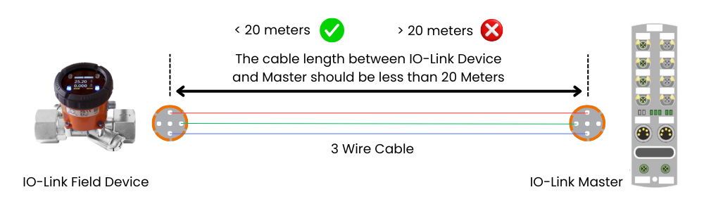
With IO-Link, the same sensor sends its process value digitally, simultaneously transmits up to 32 bytes of diagnostic data, and can receive parameter settings from the PLC system , all over a standard M12 cable no longer than 20 metres. The IO-Link Master collects this data from up to 8 sensors per module and passes it up to the automation system via standard fieldbus networks such as PROFINET, PROFIBUS, EtherNet/IP or Modbus.

How IO-Link Works: Master, Device and the 3-Wire Connection
The IO Link system has three physical components working together. Understanding each one makes the whole system clear.
IO-Link Four Operating Modes: From Simple Digital to Full Smart Communication
An IO-Link Master port can operate in four different modes. This is what makes IO-Link backward compatible with existing sensors , you can connect a conventional sensor to an IO-Link Master port and it just works as a standard digital input, with the option to upgrade to full IO-Link communication simply by replacing the sensor with an IO-Link capable device.
Full bidirectional digital communication. The master and device exchange process data, diagnostic data, parameters and identification data in every cycle. This is the full smart sensor capability. Requires an IO-Link capable device. Communication speed: COM1, COM2 or COM3 (up to 230.4 kbps).
The C/Q pin operates as a standard digital input or output. No IO-Link communication takes place. Any conventional sensor (NPN or PNP digital output) can be connected in this mode. The master port behaves exactly like a standard digital I/O point. Used for non-IO-Link sensors to preserve backward compatibility.
The port is configured as a digital input only. The connected device is a conventional digital sensor outputting a standard on/off signal. No IO-Link protocol. This mode is explicitly configured at the master port level, distinguishing it from SIO mode where auto-detection may apply.
The port is configured as a digital output only. The master sends a switching signal to drive an actuator, indicator lamp or solenoid valve. No IO-Link protocol. Again, the master port controls the connected device using a standard digital signal on the C/Q line.
IO-Link Four Types of Data Transmitted
The primary measurement value , the same value you would have got from a 4-20 mA signal, but now in digital form with much higher resolution. For a pressure sensor: the current pressure reading in Pa or bar. Transmitted every IO-Link cycle (minimum every 400 microseconds at COM3). Sent automatically, without the master needing to request it. Up to 32 bytes of process data per cycle.
Configuration parameters read from or written to the device. Examples: set the pressure sensor alarm threshold, change the measurement unit from bar to PSI, configure the output switching point, set the damping time constant. Parameters are stored in the device non-volatile memory. The master can upload parameters from the device (backup) or download parameters to a replacement device (restore after swap).
Static identification data stored in the device: manufacturer name, device name, serial number, hardware version, firmware version. This data is used by the master for automatic device identification. If a sensor is replaced, the master detects the new device ID and can flag an alarm if the replacement is a different model. Eliminates manual record-keeping of sensor serial numbers.
Asynchronous notifications sent by the device to the master when something abnormal occurs. Examples: sensor contamination detected, temperature at sensor head above limit, LED source degradation warning, calibration overdue, supply voltage low. Events are sent immediately when they occur, not on a fixed cycle. The master forwards events to the PLC and SCADA for display and logging , enabling predictive maintenance without manual inspection.
Video: How IO-Link Works Explained
IO-Link Standard: IEC 61131-9 and IODD Device Description
IO Link vs Conventional Wiring: What Changes for the Technician
| Feature | Conventional 4-20 mA / Digital I/O | IO Link Smart Sensor |
|---|---|---|
| Cable type | Screened analog cable (4-20 mA) or 3-wire digital sensor cable | Standard unshielded 3-wire M12 sensor cable |
| Signal resolution | 12-16 bit ADC in the AI card | Up to 32-bit digital resolution from device , no ADC error |
| Process value | One analog value (current) | Multiple process values in one cycle (e.g. pressure + temperature + status) |
| Sensor diagnostics | None , sensor failure shows only as wrong reading | Full diagnostic events: contamination, drift, voltage low, calibration due |
| Remote configuration | Requires field visit and handheld configurator | Parameters changed from PLC/SCADA without visiting the field |
| Sensor replacement | Manual re-configuration at the device after swapping | Master automatically downloads saved parameters to the new device (auto-restore) |
| Serial number tracking | Manual logbook required | Master reads serial number automatically , full traceability |
| Wiring cost | Higher for analog (screened cable, AI card cost) | Lower , same cable as digital I/O, DI/DO card costs less than AI card |
IO Link Benefits That Make It the Future of Field Instrumentation
Sensor diagnostics and event data reach the SCADA in real time , detect sensor fouling or drift before it causes a process upset.
IODD files auto-configure the device structure. Sensor parameters are downloaded automatically on first connection.
Replace a faulty sensor and the master restores all saved parameters automatically. No re-calibration or re-configuration needed.
Multiple process values per device. A flow meter can report flow rate, temperature, fluid conductivity and total volume in one cycle.
No screened cable, no separate power cable. Same 3-wire M12 cable for every IO Link device regardless of manufacturer.
The IO Link Master connects to PROFINET, EtherNet/IP, PROFIBUS, CC-Link or any other fieldbus. IO-Link is fieldbus-agnostic.
Quick FAQs: IO Link Working Principle
- PROFIBUS vs PROFINET: Which Industrial Network Should You Choose?
- RS232 vs RS485: Serial Communication Standards Compared
- 4-20 mA vs IO-Link: When Analog Still Makes Sense
- Cold Loop and Hot Loop Testing: Commissioning IO Link Instrument Loops
- HART Protocol: How It Compares to IO Link for Smart Sensor Communication
External References
- IO Link Consortium: What Is IO-Link?
- IODD Finder: Download Device Description Files for IO-Link Sensors
- SICK: IO-Link Basics , Technology and Applications
- Balluff: IO Link Know-How Centre
What we learn today
- IO Link (IEC 61131-9) is a point-to-point digital communication standard. One IO-Link Master port connects to exactly one smart sensor or actuator over a standard 3-wire M12 cable, maximum 20 metres. The master connects upward to PROFINET, EtherNet/IP or other fieldbus. It is NOT a fieldbus itself.
- Four operating modes: IO Link COM mode (full smart communication), SIO mode (standard digital I/O , backward compatible with conventional sensors), DI mode (digital input), DO mode (digital output). Four data types transmitted: process data (measurement value), service data (parameters), device data (serial number, model) and events (diagnostic alarms).
- Key advantages over 4-20 mA: multiple process values per cycle, rich diagnostic events for predictive maintenance, remote parameter configuration without field visits, automatic parameter restore when a sensor is swapped, and automatic serial number tracking , all over the same 3-wire cable at no additional cabling cost.