
A loose lug, a cracked strand or a few shorted turns can hide inside a motor that still passes its insulation test. Measuring the DC resistance of each winding accurately, and comparing the phases, exposes these faults before they burn the machine.
A winding resistance test measures the small DC resistance of motor and transformer windings to find loose connections, open strands and shorted turns. Done with the right instrument and a temperature correction, it gives a reliable health check in minutes.
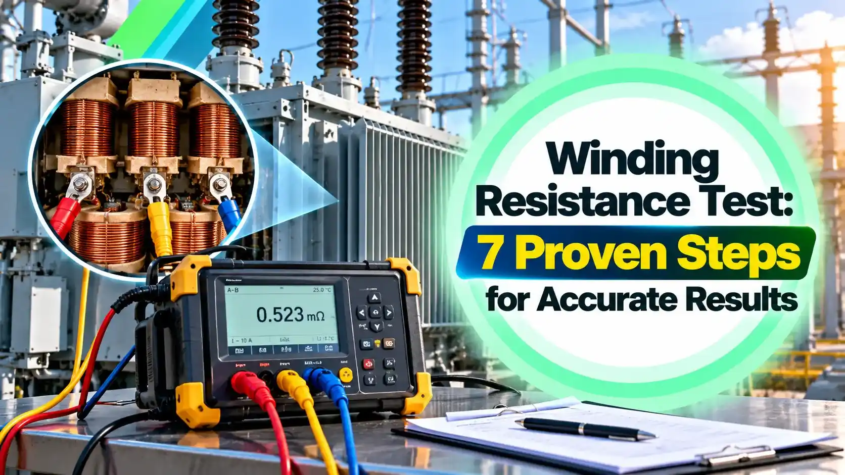
What Is a Winding Resistance Test?
A winding resistance test is the measurement of the DC resistance of each winding of a motor, generator or transformer, followed by a comparison between phases and with earlier or factory values. It checks the copper path itself, unlike an insulation resistance test, which checks the insulation around it.
The values are small, often below 1 Ω for large machines, so a normal multimeter is not accurate enough. The test follows Ohm law, with a known DC current passed through the winding and the voltage drop measured across it.

What the Test Can Reveal
Electrom Instruments explains that resistance measurements can find resistive connections inside or outside the machine, partial breaks in multi strand coils, open or shorted coils and wrong wire gauges. Some of these faults are not always visible to a surge test alone.
One phase reads higher because of a loose lug, corroded terminal or poor brazed joint.
Resistance rises when some parallel strands or a parallel path break.
One phase reads lower because turns are bypassed through damaged insulation.
The relative balance between phases matters more than the absolute value. In a healthy induction motor, all three phases are wound identically, so their resistances should be almost equal.
Copper has a temperature coefficient of about 0.0039 per °C, according to Electrom Instruments. A 10 °C change in winding temperature therefore changes the reading by roughly 4 percent.
Why the 4 Wire Kelvin Method Is Used
In a 2 wire winding resistance test, the leads and clamp contacts add their own resistance, which can be as large as the winding itself. The 4 wire or Kelvin method uses one pair of leads to inject current and a separate pair to sense voltage right at the terminals.
Almost no current flows in the sense leads, so their resistance causes no error. The same idea is used in 2 wire, 3 wire and 4 wire RTD circuits, where lead resistance would spoil a temperature reading.
The Megger guide to low resistance testing states that the four wire method eliminates errors due to lead and contact resistances. It calls it the most accurate method for circuits below 10 Ω.
Place the voltage sense clips inside the current clips, closest to the winding. That way the contact resistance of the current clamps stays outside the measured section.
Instruments for the Measurement
For a winding resistance test, a micro ohmmeter or a dedicated meter is used, since both can supply a steady DC current and resolve microohms. Older workshops used a Kelvin double bridge, a relative of the Wheatstone bridge, and some still keep one for reference.
DV Power recommends that the test current should not exceed 10 percent of the nominal winding current, to avoid heating the winding during the test. Its RMO50M model supplies 5 mA to 50 A DC and measures from 0.1 µΩ to 1000 Ω.
Electrom Instruments states that its iTIG tester uses 4 wire Kelvin clamps and measures from a few microohms to 2 kΩ. Choose a range where the reading has at least four significant digits.
7 Steps to Perform a Winding Resistance Test
Always apply lockout tagout before touching the terminals, and remember that a large motor can also generate voltage if its shaft is turned by the load. Clean the terminal studs, because paint or oxide adds contact resistance.
Take the reading only after it settles, since the winding inductance delays the current rise. On a large motor this takes a few seconds, while a big transformer may need minutes.
Unbalance Limits and How to Judge Them
Phase unbalance is the difference between the highest and lowest reading divided by the average reading. Electrom Instruments notes that industry standards specify phase balance tolerances from 2 to 5 percent.
Many repair shops use the tighter figure of about 2 percent for low voltage motors. Always compare with the factory report or the last winding resistance test on the same machine, and also check the motor insulation class when judging overheating history.
| Observation | Likely Cause | Action |
|---|---|---|
| One phase high | Loose or corroded connection, broken strand | Clean and retorque, then retest |
| One phase low | Shorted turns in that phase | Surge test and inspect windings |
| All phases high | Hot winding or wrong reference temperature | Correct for temperature, recheck |
| Reading drifts | Clamp contact poor or inductance not settled | Clean contacts, wait longer |
| Open circuit | Broken lead or burnt winding | Trace circuit, rewind if needed |
Star and Delta Connection Readings
If all six winding ends are available, measure each phase separately between U1 and U2, V1 and V2, and W1 and W2. If only three terminals are available, the line readings depend on the star or delta connection.
Delta: Line reading = 2 ÷ 3 × Phase resistance, so Phase = 1.5 × Line
Example:
Delta motor, three line readings of 0.80 Ω
Phase resistance = 1.5 × 0.80 = 1.20 Ω
The same windings in star would read 2 × 1.20 = 2.40 Ω between lines
In delta, the line reading is lower because the measured phase is in parallel with the other two phases in series. Unbalance on line readings is still useful, but one faulty phase affects two of the three readings.
Temperature Correction Formula
Resistance rises with temperature, so winding resistance test readings taken at different temperatures cannot be compared directly. The Megger guide gives the copper relation R2 ÷ R1 = (234.5 + T2) ÷ (234.5 + T1).
Unbalance % = (R max minus R min) ÷ R average × 100
K = 234.5 for copper, 225 for aluminium
Example:
R1 = 1.250 Ω, R2 = 1.262 Ω, R3 = 1.247 Ω at 30 °C
R average = 1.253 Ω
Unbalance = (1.262 minus 1.247) ÷ 1.253 × 100 = 1.20 %
Factor to 75 °C = 309.5 ÷ 264.5 = 1.1701
R average at 75 °C = 1.253 × 1.1701 = 1.4662 Ω
A reference of 75 °C is common in transformer test reports and many motor test sheets, while some users prefer 25 °C. Use the same reference every time so that the trend stays meaningful.
Winding Resistance Test Calculator
The constant 234.5 is the temperature in °C below zero at which the resistance of annealed copper would extrapolate to zero. Aluminium uses a value of about 225 for the same reason.
Second Worked Example: Transformer HV Winding
A distribution transformer HV winding reads 2.10 Ω at an oil temperature of 32 °C. Corrected to 75 °C, it becomes 2.10 × 309.5 ÷ 266.5 = 2.44 Ω, which is then compared with the factory value in the transformer routine test report.
On transformers, measure every tap position, because a worn tap changer contact shows up as a jump on one tap only. Also check the turns ratio, since shorted turns change both resistance and ratio.
On a large transformer, never remove the test leads while current is flowing. The stored magnetic energy can produce a dangerous voltage, so always wait for the instrument to complete its discharge.
Standards and Good Practice
IEEE 118 is the general test code for resistance measurements, while IEEE 112 and IEC 60034 cover motor testing that includes a winding resistance test. For transformers, IEC 60076 part 1 lists winding resistance among the routine tests.
- Motor isolated, locked out and proven dead.
- Cables and neutral links removed from the terminals.
- Winding temperature recorded with a calibrated thermometer.
- Terminals cleaned, sense clips inside current clips.
- Test current below 10 percent of rated current.
- Reading stable before recording.
- Values corrected to a fixed reference temperature.
- Results compared with history and between phases.
- Finds loose joints and open strands quickly.
- Simple, low voltage and non destructive.
- Works on motors, generators and transformers.
- Gives numbers that trend well over years.
- Cannot detect insulation weakness to earth.
- Very small shorts may change resistance too little.
- Needs accurate temperature data.
- Large inductive windings take time to settle.
Where Engineers Use It
When a thermal overload relay or motor protection relay trips on unbalance, a winding resistance test quickly shows whether the cause is inside the motor or in the supply. Combine it with insulation and surge tests for a full picture.
Megger Guide to Low Resistance Testing
Motor Winding Test Video
Winding Resistance Test FAQ
It is the measurement of the DC resistance of each winding in a motor, generator or transformer. The readings are compared between phases and with earlier or factory values.
A healthy three phase machine shows almost equal values on all phases when tested at the same temperature. A clear difference points to loose joints, broken strands or shorted turns.
Winding resistance is often below 1 Ω, so lead and contact resistance can cause large errors. The 4 wire method separates the current leads from the voltage sense leads.
The sense leads carry almost no current, so their resistance does not affect the reading. Megger describes it as the most accurate method for circuits below 10 ohms.
Electrom Instruments notes that industry standards specify balance tolerances from about 2 to 5 percent. Many repair shops apply about 2 percent to low voltage motors.
Unbalance is the difference between the highest and lowest reading divided by the average. Always compare with the machine history as well as with the fixed limit used by the standard or repair shop.
Multiply the measured value by the ratio of 234.5 plus the reference temperature to 234.5 plus the test temperature. Use 225 in place of 234.5 for aluminium windings.
For example, an average of 1.253 Ω measured at 30 °C becomes about 1.466 Ω at a 75 °C reference. Always record the winding temperature with each set of readings in the test record.
DV Power recommends that the test current should not exceed 10 percent of the rated winding current. Higher current heats the winding and raises the reading during the test.
Too little current gives a small voltage drop and a noisy reading. Pick a current that gives a stable reading with at least four significant digits.
In star, the line reading equals twice the phase resistance. In delta, it equals two thirds of the phase resistance, because the other two phases form a parallel path.
When all six ends are available, measure each phase directly between its two terminals. This removes any doubt about the connection and gives the cleanest comparison.
Yes, the winding resistance test is a routine test for power and distribution transformers and is listed in IEC 60076 part 1. Every tap position should be measured to check the tap changer contacts.
Large transformer windings need time for the current to stabilise because of high inductance. Never disconnect leads before the instrument finishes discharging the stored energy.
Related Articles
- Insulation Resistance Test With a Megger
- Star vs Delta Connection
- Transformer Routine and Type Tests
- Motor Protection Relay Types
- How an AC Induction Motor Works
External References
- A Guide to Low Resistance Testing, Megger
- Winding Resistance Measurement Method, Electrom Instruments
- Four Terminal Sensing, Wikipedia
What We Learn Today
- A winding resistance test measures the DC resistance of each phase winding to find loose joints, broken strands and shorted turns in motors and transformers.
- The 4 wire Kelvin method removes lead and contact resistance errors, and test current should stay below 10 percent of the rated winding current.
- Correct readings with (234.5 + T ref) ÷ (234.5 + T test) for copper and judge phase unbalance against about 2 to 5 percent.