
A small metal plate riveted to the motor frame holds almost everything you need to select a starter, size a cable and set an overload relay. Learning to read it correctly saves hours of guesswork during commissioning and breakdowns.
Every induction motor carries a rating plate that describes how it was designed to run. Those numbers decide protection settings, cable size, spare parts and whether a replacement motor will really fit.
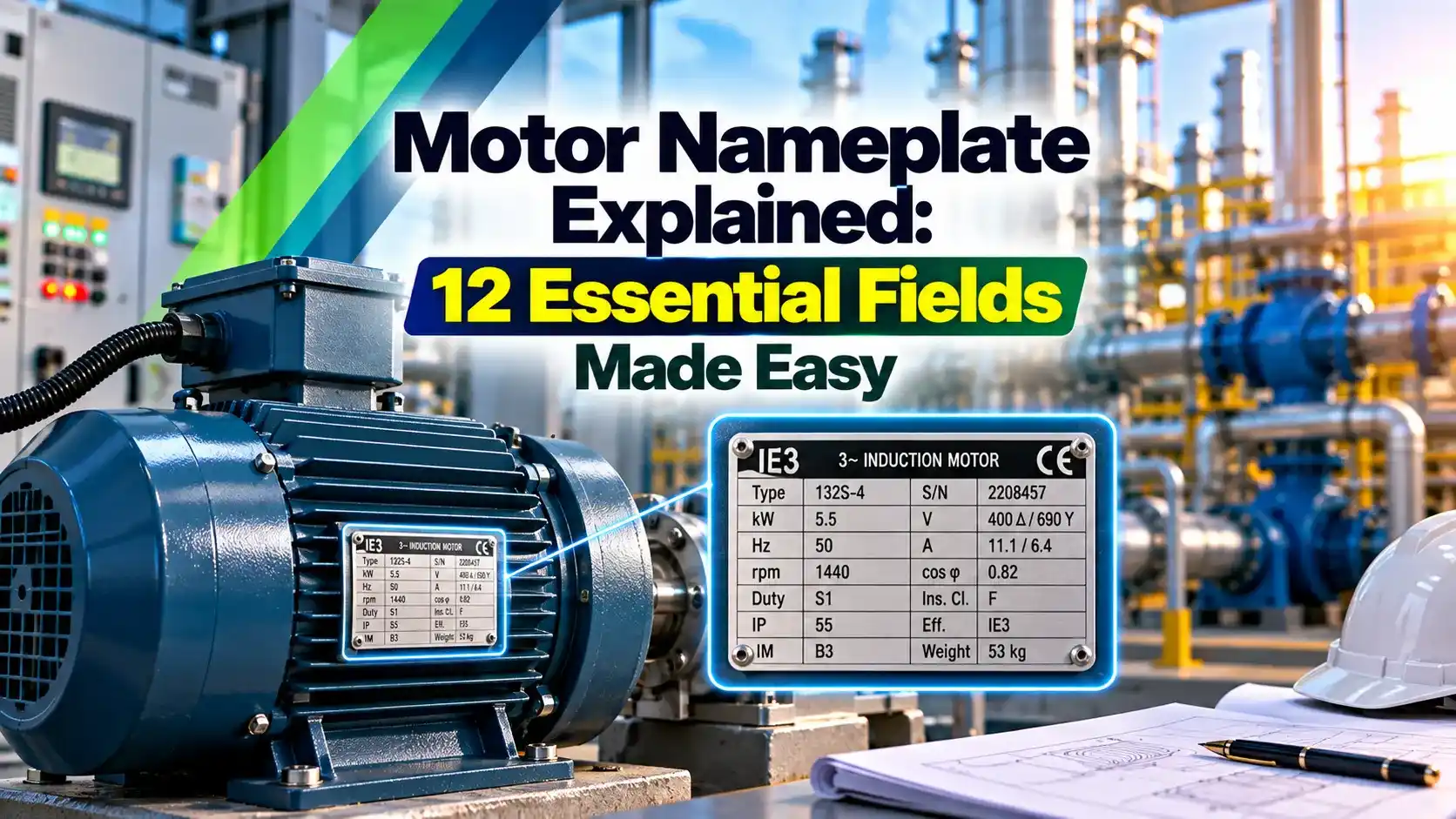
What Is a Motor Nameplate?
A motor nameplate is the permanent rating plate fixed to an electric motor that lists its rated output, voltage, current, speed, efficiency and construction details. It tells you the conditions under which the manufacturer guarantees the performance of the AC induction motor.
In India, three phase induction motors are built to IS 12615 for efficiency and IS 325 for general requirements, both aligned with the IEC 60034 series. Imported motors may follow NEMA MG 1, which uses horsepower and a slightly different layout.

ABB notes that the most common motor frequency in the United States is 60 Hz, while most of the rest of the world, including India, uses 50 Hz. The same motor runs about 20 percent faster on 60 Hz.
12 Essential Motor Nameplate Fields
Read the output first, because every other value relates to it. The motor nameplate kW is mechanical shaft output, not electrical input, a difference explained further in motor full load current FLC.
On the motor nameplate, voltage and current are usually printed together for each connection. A plate marked 415 V delta with 20.5 A tells you the line current you will measure in the supply cable.
Reading a Sample Motor Nameplate
| Field | Typical Entry | What It Means |
|---|---|---|
| Output | 11 kW, 15 HP | Rated shaft power |
| Voltage | 415 V Δ | Connect in delta on a 415 V supply |
| Current | 20.5 A | Full load line current |
| Speed | 1460 rpm, 50 Hz | 4 pole motor, 2.7 percent slip |
| Power Factor | cos φ 0.85 | Ratio of kW to kVA at full load |
| Efficiency | 91.4 %, IE3 | Premium efficiency class |
| Insulation | Class F, rise B | 155 °C insulation, 80 K rise limit |
| Duty and IP | S1, IP55 | Continuous duty, dust and jet protected |
| Frame | 160M | 160 mm shaft height, medium length |
| Bearings | DE 6309 2Z C3, NDE 6209 2Z C3 | Shielded ball bearings, C3 clearance |
This example is a typical 11 kW, 4 pole, 415 V motor used for pumps and fans in Indian plants. Your plate may show slightly different values, but every motor nameplate from a reputed maker carries these same fields.
The current value here is the one to use when setting the overload relay, described in thermal overload relay explained. It is also the starting point for cable sizing for motor feeders.
Photograph the motor nameplate the day a motor is installed and store it with the loop or equipment file. Paint, heat and corrosion often make the plate unreadable years later, just when you need a replacement.
Speed, Slip and Synchronous Speed
Synchronous speed depends only on supply frequency and number of poles, Ns = 120 × f ÷ P. The rotor always turns slightly slower, and that difference is called slip.
Slip % = (Ns minus N) ÷ Ns × 100
Input kW = Output kW ÷ Efficiency
I = Input kW × 1000 ÷ (√3 × V × PF)
Example from the sample plate:
f = 50 Hz, P = 4, N = 1460 rpm
Ns = 120 × 50 ÷ 4 = 1500 rpm
Slip = (1500 minus 1460) ÷ 1500 × 100 = 2.67 %
Input = 11 ÷ 0.914 = 12.04 kW
I = 12035 ÷ (1.732 × 415 × 0.85) = 19.7 A
Calculated 19.7 A against 20.5 A on the plate
The small gap between calculated and printed current comes from rounded efficiency and power factor values and manufacturing tolerance. Slip behaviour under load is covered in induction motor slip explained.
A 2 pole motor at 50 Hz runs near 2900 rpm, a 4 pole near 1450, a 6 pole near 960 and an 8 pole near 720. So the rpm on the motor nameplate quickly reveals the pole count.
Slip and Current Check Calculator
Voltage, Connection and Current
A motor nameplate often shows two voltages with two symbols, such as 400 V Δ and 690 V Y. The motor is connected in delta for 400 V and in star for 690 V, and the current for each connection is printed beside it.
Star and delta wiring of the terminal box is shown in star vs delta connection. A motor rated 415 V delta is suitable for a star delta starter, as compared in DOL vs star delta starter.
According to CED Engineering course notes, standard induction motors are designed to run within plus or minus 10 percent of nameplate voltage. Outside that range current, heating and torque change noticeably.
Efficiency, IE Class and Power Factor
Standard efficiency, older designs.
High efficiency.
Premium efficiency.
Super premium efficiency.
The IE class comes from IEC 60034 30 1 and is adopted in India through IS 12615, with IE5 now defined as ultra premium. Test methods and class limits are explained in motor efficiency classes IEC 60034.
Power factor on the motor nameplate is at full load, and it falls sharply at light load. Its link to kVA and reactive power is covered in power factor, kW, kVA and kVAR.
An 11 kW motor running 8000 hours a year uses roughly 96000 kWh of electricity. Moving from IE2 to IE3 saves close to 1.6 percentage points of efficiency, which is well over 1000 kWh per year.
Insulation Class, Ambient and Service Factor
Insulation class states the maximum hot spot temperature the winding materials can withstand: Class B 130 °C, Class F 155 °C and Class H 180 °C. ABB explains that Class F insulation is suitable for a 105 °C rise by resistance at a 40 °C ambient.
Many motors use Class F insulation but are designed for Class B rise of 80 K, which leaves a thermal margin for longer life. More detail is in motor insulation classes.
Ambient temperature on the motor nameplate is usually 40 °C, but many Indian plants specify 45 or 50 °C. Above the rated ambient or above 1000 m altitude, the motor must be derated.
Service factor appears mainly on a NEMA motor nameplate. ABB states that a 1.15 service factor lets a motor handle infrequent loads up to 15 percent above rated horsepower, though IEC motors usually show 1.0.
Duty Types S1 to S9
| Duty | Name | Typical Use |
|---|---|---|
| S1 | Continuous running | Pumps, fans, compressors |
| S2 | Short time duty, such as S2 30 min | Valve actuators, gates |
| S3 | Intermittent periodic | Hoists with rest periods |
| S4 | Intermittent periodic with starting | Cranes, frequent starts |
| S5 | Intermittent with electric braking | Positioning drives |
| S6 | Continuous operation periodic duty | Machine tools with idle periods |
| S7 | Continuous with electric braking | Reversing drives |
| S8 | Continuous with speed and load changes | Multi speed drives |
| S9 | Non periodic load and speed variation | Inverter fed variable loads |
Most industrial motors carry S1 on the motor nameplate, and using an S1 motor for frequent starts can overheat the rotor. Crane and hoist motors carry S3 or S4 with a cyclic duration factor such as 40 percent.
IP Rating, Frame Size and Bearings
The first IP digit is protection against solids and the second against water, so IP55 means dust protected and safe against water jets. The full code table is in IP rating explained.
For IEC motors, the frame number is the shaft height in millimetres, so a 160M frame has its shaft centre 160 mm above the feet. The CED Engineering notes add that for NEMA foot mounted motors, the first two frame digits divided by four give shaft height in inches.
Bearing numbers on the motor nameplate, such as 6309 2Z C3, identify a deep groove ball bearing with two shields and C3 internal clearance. Keep matching bearings in stores, and note that roller bearings at the drive end suit belt drives.
When replacing a motor, match frame size, shaft diameter, flange type and mounting code, not just kW and rpm. A different frame can mean new base plates and couplings on site.
How to Use a Motor Nameplate in the Field
Protection relays for bigger motors also use motor nameplate data for thermal models, see motor protection relay types. Before first start, test the winding with an insulation resistance megger test.
- Supply voltage and frequency match the motor nameplate.
- Terminal connection matches the voltage marked for star or delta.
- Overload relay set at or slightly below full load current.
- Cable and breaker sized from full load current.
- Duty type suits the start and stop pattern.
- IP rating suits the location, including washdown areas.
- Ambient and altitude within the rated limits.
- Correct protection settings.
- Right cable and starter selection.
- Faster replacement and spares.
- Energy audits with real efficiency.
- Plates fade or get painted over.
- Values are at rated load only.
- Rewound motors may differ from plate data.
- Drive fed operation not fully described.
Nameplate Standards Course PDF
Nameplate Walkthrough Video
Motor Nameplate FAQ
It lists rated output, voltage, full load current, frequency, speed, power factor and efficiency at the rated operating point. It also shows insulation class, duty type, IP rating, frame size and often the bearing numbers.
These values define how the manufacturer designed the motor to run safely. They are the basis for protection settings, cable sizing and starter selection on site.
The kW value is the mechanical output available at the motor shaft. Electrical input is always higher because of copper, iron, friction and stray losses inside the motor.
Divide the output by efficiency to get the electrical input power. For example, 11 kW at 91.4 percent efficiency needs about 12.04 kW of input from the supply.
First calculate synchronous speed as 120 times frequency divided by the number of poles. Then subtract the rated rpm and divide the difference by the synchronous speed.
A 4 pole, 50 Hz motor rated at 1460 rpm has a synchronous speed of 1500 rpm. Its slip is therefore about 2.67 percent at full load, which is typical for this size.
It means the stator windings must be connected in delta for a 415 V three phase line supply. Each phase winding then sees the full line voltage during normal running.
Such motors are suitable for star delta starting to reduce starting current. In star, each winding sees only about 58 percent of the line voltage during the start.
Insulation class is the maximum temperature the winding materials can survive over their design life. Temperature rise is how much the winding heats above the ambient temperature at full load.
A Class F motor designed for Class B rise runs well below its insulation limit. This thermal margin noticeably extends winding life in hot Indian plants.
S1 means the motor is rated for continuous running at a constant load. It reaches thermal equilibrium and can then run indefinitely without overheating.
IP55 means protection against harmful dust deposits and against low pressure water jets from any direction. It is the most common enclosure rating for industrial motors in Indian pumps, fans and conveyors.
The printed current includes the exact efficiency and power factor measured during type testing. Hand calculations use rounded values and ignore manufacturing tolerance on both figures.
A difference of a few percent is normal and not a cause for concern. A large gap usually means a wrong input value, a misread plate or a rewound motor.
Related Articles
- Motor Full Load Current FLC
- Motor Efficiency Classes IEC 60034
- Motor Insulation Classes
- Induction Motor Slip Explained
- Star vs Delta Connection
External References
- Understanding Motor Nameplate Information, NEMA vs IEC Standards, CED Engineering
- How to Read a NEMA Motor Nameplate, ABB
- Induction Motor, Wikipedia
What We Learn Today
- A motor nameplate gives rated kW output, voltage and connection, full load current, rpm, power factor, efficiency class, insulation, duty, IP rating and frame.
- Synchronous speed equals 120 times frequency divided by poles, and the gap to rated rpm gives slip, typically 1 to 5 percent at full load.
- Input current can be checked from kW, voltage, power factor and efficiency, then used for overload settings, cable sizing and starter selection.