
Most analyzer problems in a plant are not caused by the analyzer at all but by the sample that reaches it. A well designed sample system delivers a clean, representative and timely sample, which is the real foundation of good process analytics.
Process fluid is usually too hot, too dirty, too wet or at too high a pressure for an analyzer. Sample handling hardware extracts it, conditions it and returns or vents it without changing its composition.
What Is a Sample Conditioning System?
A sample conditioning system is the set of probes, tubing, filters, regulators, coolers and valves that takes fluid from the process and delivers it to an online analyzer in a form the analyzer can measure. It serves the instruments described in gas analyzers explained as well as liquid analyzers.
The goal of any sample conditioning system is a sample that is representative of the process, compatible with the analyzer and delivered quickly. Removing a component that should be measured, or adding one through leaks or adsorption, ruins the result.

The importance of analytical measurements for quality, safety and emissions is why sample hardware deserves the same design care as the analyzer itself.
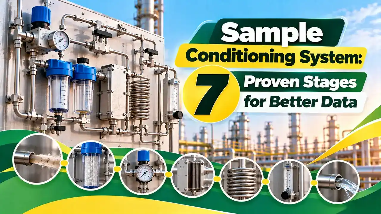
7 Proven Stages from Tap to Analyzer
Each stage of a sample conditioning system must preserve composition. A cold spot can condense heavy hydrocarbons, and a wet filter can dissolve soluble gases such as ammonia or sulphur dioxide.
Fast Loop and Bypass Design
Control Global describes the fast loop as an external loop with minimal conditioning that circulates sample close to the analyzer, from which the actual analyzer sample is drawn. The excess flow returns to the process or to flare.
The same article recommends a sample velocity of 1 to 2 m/s so components stay suspended. It also advises purging the system about three times for each analyzer cycle to remove old sample from dead volumes.
Calculating Sample Lag Time
Control Global defines total lag as analyzer cycle time plus sample transport time from the tap to the sensor. Swagelok notes that the industry standard target is about one minute of response.
Lag time t = V ÷ Q
Example:
ID = 4 mm, L = 30 m, Q = 1.5 L/min at line conditions
V = 0.7854 × 0.004² × 30 = 0.000377 m³ = 0.377 L
t = 0.377 ÷ 1.5 = 0.251 min = 15.1 s
Velocity = Q ÷ area = 1.99 m/s
Size every sample conditioning system with flow at actual line pressure and temperature, not at standard conditions. Gas at 10 bar gauge occupies about one eleventh of its atmospheric volume, so the same standard flow moves much more slowly through a high pressure line.
Transport Lag Calculator
The Yokogawa lag time note warns that unpurged volumes in filters and dead legs add capacity lag on top of line transport. Add those volumes, divided by their flow, to the tubing figure.
Liquid Samples and Vaporisation
Swagelok points out that after a vaporising regulator the vapour flow can be more than 300 times the liquid flow. The liquid section therefore moves very slowly, so keep it as short as possible and place the vaporiser near the tap.
Heated lines prevent condensation of heavy components, using methods from heat tracing in piping systems. Water content must be controlled too, and the ideas in dew point risks in instrument air apply equally to sample gas.
Matching the Conditioning to the Analyzer
| Analyzer | Key Conditioning Need | Typical Hardware |
|---|---|---|
| Gas chromatograph | Stable pressure, no liquids | Regulator, filter, stream selector |
| Zirconia oxygen | Often in situ, minimal | Probe filter, calibration port |
| NDIR gas | Dry, particle free sample | Chiller, pump, fine filter |
| Stack CEMS | Hot wet or dry extractive | Heated probe and line, cooler |
A process gas chromatograph is very sensitive to pressure changes, while a zirconia oxygen analyzer is often mounted in situ with little conditioning.
An NDIR gas analyzer usually needs a dry sample, and a CEMS uses heated extractive lines to keep acid gases in the vapour phase.
NeSSI Modular Sample Conditioning System Design
The New Sampling and Sensor Initiative, NeSSI, replaced tube and fitting panels with small surface mount components on a modular substrate. The mechanical interface is standardised in ANSI ISA 76.00.02, so parts from different vendors fit the same base.
- Representative, fast sample delivery.
- Protects the analyzer from dirt and liquid.
- Enables automatic calibration and validation.
- Modular NeSSI designs save space.
- Adds cost, space and maintenance.
- Poor design causes long lag.
- Dead volumes and leaks distort results.
- Filters and coolers need regular service.
Include calibration gas injection at the probe so the whole path is checked, as in oxygen analyzer calibration. For interview style revision, see analytical instruments questions and answers.
Yokogawa Lag Time Note PDF
Conditioning Hardware Video
Sample Conditioning System FAQ
Process fluid is often hot, dirty, wet or at high pressure when it leaves the tap. Most analyzers need a clean sample at controlled pressure, temperature and flow to measure correctly.
The conditioning hardware makes that possible without changing the composition of the sample. It also allows calibration gas to reach the analyzer automatically on a schedule.
A fast loop circulates a large sample flow from the tap to a point near the analyzer and then back to the process. It keeps fresh sample close to the analyzer at all times.
The analyzer draws only a small slip stream from this loop through its own conditioning. That cuts transport lag without pushing excess flow through the analyzer itself.
Lag time equals the internal volume of the sample line divided by the actual volumetric flow. Add the volumes of filters, coolers and other components as well.
Total system response also includes the analyzer cycle time on top of transport. Swagelok notes that a gas chromatograph may take five to 10 minutes per analysis.
Control Global suggests a velocity of 1 to 2 m/s in sample transport lines. That range keeps components suspended and keeps the transport time reasonably short.
Much lower velocities let particles and droplets settle in low points of the tubing. Much higher velocities raise pressure drop and waste valuable sample to flare or drain.
Common methods are compressor chillers, Peltier coolers and membrane permeation dryers. Coalescing filters usually remove liquid droplets before these drying stages.
Be careful with water soluble gases, which can dissolve in the condensate and be lost. In such cases a hot wet extractive system is often the better choice.
NeSSI is the New Sampling and Sensor Initiative for modular analyzer sample systems. Components mount on a standard substrate instead of being joined with tubing and fittings.
This reduces overall size, internal dead volume and the number of leak points. It also makes replacing a filter, valve or regulator much quicker for technicians.
Ideally, calibration gas enters at the probe or as close to it as possible. The gas then travels through the whole conditioning path just like the real sample.
This checks for leaks, adsorption and lag, not only the response of the analyzer. It gives a true picture of the complete measurement chain from tap to reading.
Related Articles
- Gas Analyzers Explained
- Gas Chromatograph Basics
- CEMS Continuous Emissions Monitoring
- Heat Tracing in Piping Systems
- Oxygen Analyzer Calibration
External References
- Lag Time Simplified, Yokogawa
- Basics of Analyzer Sample Systems, Control Global
- Process Analytical Technology, Wikipedia
What We Learn Today
- A sample conditioning system must deliver a representative, clean and timely sample, because most analyzer faults begin in the sample path rather than the analyzer.
- Lag time equals line and component volume divided by actual flow, and a fast loop keeps fresh sample close to the analyzer.
- Filters, regulators, coolers, dryers and stream selectors must preserve composition, while NeSSI modular hardware reduces dead volume and leak points.