
A motor that trips on startup after sitting idle for months is usually telling you its insulation absorbed moisture, and Insulation Resistance Testing with a megger is how you confirm that before reenergizing anything.
Insulation Resistance Testing with a megger applies a DC voltage across a conductor's insulation and measures the leakage current, giving a megohm reading that shows whether the insulation is dry and sound or contaminated and failing.
This is worth doing before any earthing work too, since a Single Line Diagram showing every isolation point makes it far easier to identify exactly what needs to be deenergized first.
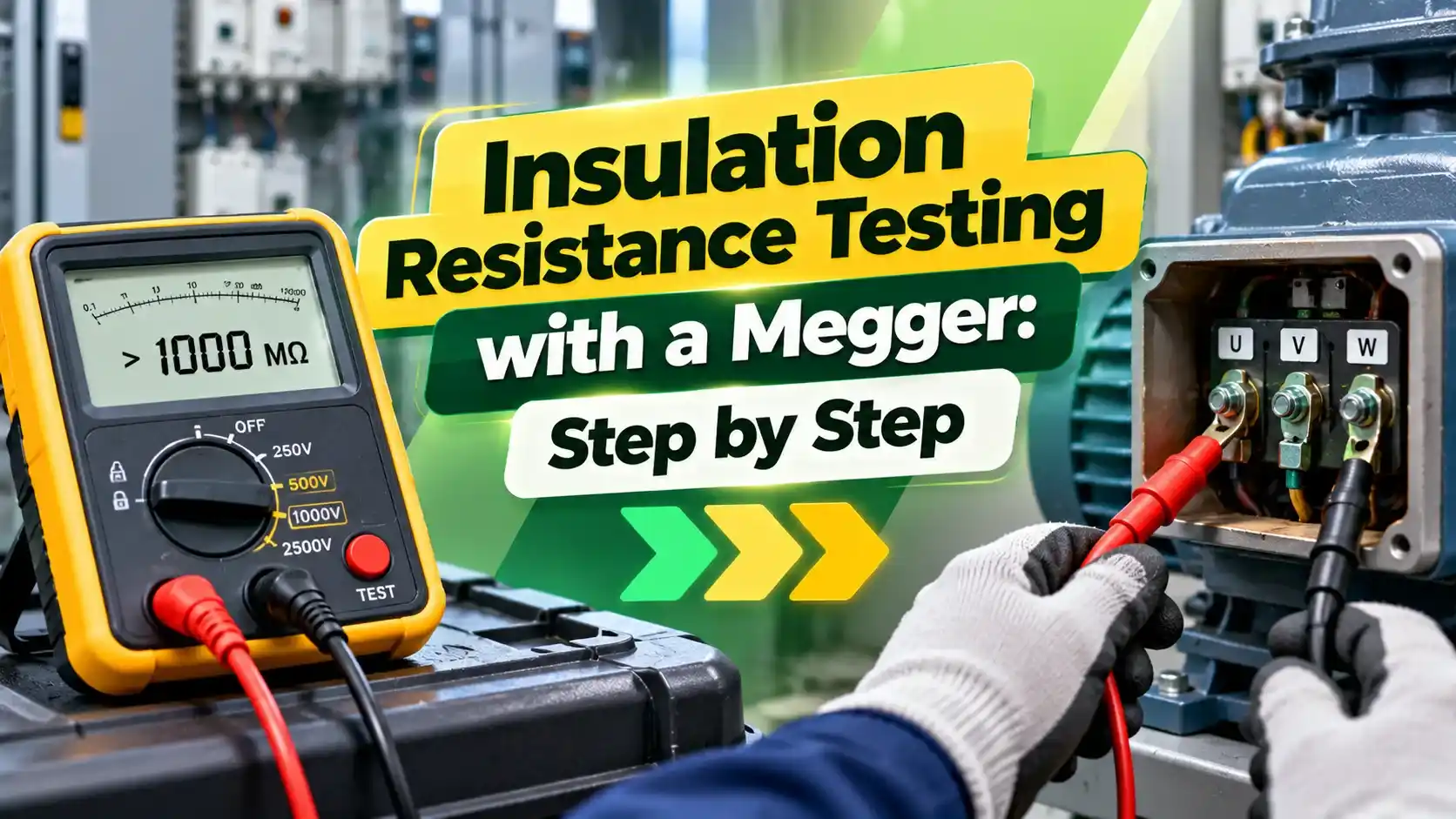
Insulation Resistance Testing
Insulation Resistance Testing, often shortened to IR testing, works by applying a steady DC voltage between a conductor and earth, or between two conductors, then measuring the tiny leakage current that flows through the insulation to calculate resistance in megohms.
Good insulation blocks nearly all of that current, giving a high megohm reading, while damp, dirty, or degraded insulation lets more current leak through, giving a lower reading that gets worse as the problem progresses.
The megger itself is simply a hand cranked or battery powered device that generates the test DC voltage and reads the resulting current directly in megohms, no separate voltmeter or ammeter is ever needed to correctly interpret the display.
IR Testing Step by Step
Skipping step two is the single most common way to damage a megger or give an inexperienced technician a nasty shock, cables and motor windings hold a genuine charge after testing and after being deenergized.
Why the Discharge Steps Matter
Long cables and motor windings behave like capacitors, storing charge from the test voltage itself. That stored energy has nowhere to go once the megger disconnects, so the conductor stays live at a dangerous voltage until something drains it away.
A dedicated discharge resistor built into most modern meggers handles this automatically at the end of a test cycle, but older or basic units may need a manual shorting stick applied by someone who knows exactly what they are doing.
Never assume a device has fully discharged just because the meter dropped to zero, a truly safe conductor should also be verified with a separate voltage tester before bare hands or tools touch it directly, every single time.
Recording a Baseline
The very first IR test on a new piece of equipment is worth recording carefully as a baseline, since every future reading gets compared against it rather than against a generic industry number.
A motor that reads 200 megohms new and drops to 20 megohms two years later has lost 90 percent of its insulation quality, even though 20 megohms alone might still look perfectly acceptable against a simple pass or fail chart.
Logging that baseline in the same maintenance record used for vibration or thermal readings keeps insulation trending visible alongside every other health indicator already tracked for that same piece of asset.
Selecting the Correct Test Voltage
| Equipment Rating | Recommended Test Voltage |
|---|---|
| Up to 500V | 500V DC |
| 500V to 1000V | 1000V DC |
| Above 1000V | 2500V DC or higher |
Interpreting the Reading
Temperature Correction
Insulation resistance readings drop as winding temperature rises, roughly halving for every ten degree Celsius increase above the reference temperature the manufacturer used when publishing minimum values.
A hot motor tested right after shutdown can read misleadingly low even with perfectly healthy insulation, so either let equipment cool to a standard reference temperature first or apply a correction factor before comparing the reading against a minimum value.
Recording the actual winding temperature alongside every reading turns an otherwise confusing result into a genuinely useful data point instead of a false alarm or, worse still, a false pass.
Where IR Testing Gets Used
Insulation Resistance Testing is one of the few checks that catches a developing fault long before it trips a breaker or causes a shutdown, which is why so many maintenance programs schedule it as routine preventive work rather than only after a failure.
Common Mistakes in IR Testing
The guard terminal on a megger diverts surface leakage current away from the main measurement, giving a truer reading of the insulation's actual internal condition rather than a number distorted by a dirty or damp cable termination.
A quick wipe down of the termination surface before testing solves many low readings that have nothing to do with the actual insulation underneath, so it is genuinely worth trying before condemning a whole cable outright based on just one poor result.
Testing Cables vs Testing Motors
A long cable run behaves differently under Insulation Resistance Testing than a compact motor winding does, mainly because of capacitance. A long cable stores more charge during the test and needs a longer discharge time afterward before it is safe to handle.
Motor windings, by contrast, are more sensitive to test voltage exceeding their rating, so confirming the winding's actual insulation class before selecting a test voltage matters more for a motor than it typically does for a simple feeder cable.
Cable manufacturers publish a maximum test voltage for each insulation type. Exceeding it during Insulation Resistance Testing can stress the insulation in ways that only show up as a failure much later.
That published limit is always worth checking carefully rather than simply assuming a higher voltage always gives a cleaner, more trustworthy final result.
Insulation Resistance Test vs Continuity Test
Insulation Resistance Test
Uses high DC voltage to check how well insulation blocks current, measured in megohms, confirms insulation quality.
Continuity Test
Uses low voltage to confirm an unbroken conductive path exists, measured in ohms, confirms wiring correctness.
The two tests answer different questions and both clearly belong in a thorough commissioning checklist, a continuity test confirms the circuit is wired correctly while an IR test confirms that wiring is safely insulated from everything else around it.
Insulation Resistance Test vs Hipot Test
A hipot, or high potential, test pushes voltage well beyond an IR test's level specifically looking for a breakdown rather than measuring resistance, and it can stress or damage marginal insulation that an ordinary IR test would pass safely.
Most routine maintenance programs stick with Insulation Resistance Testing for that reason, reserving a hipot test for new equipment acceptance or after a major repair where confirming a true dielectric margin matters more than preserving the insulation for future service.
Choosing the right test for the right occasion, rather than defaulting to whichever meter happens to be on hand, is really the whole point of understanding clearly how these two related methods actually differ from each other.
Watch: How to Use a Megger
IR Testing FAQs
Related Articles on This Site
- Earthing Aspects in Industrial Process Plants
- Earthing Resistance Calculation
- Electrical Regulations and Standards
- What Is Arc Flash
- Static Electricity Explained
External References
What We Learn Today
- IR testing applies a DC test voltage and measures leakage current to check insulation health.
- Match the test voltage to equipment rating, and always disconnect sensitive electronics before testing.
- Track readings over time rather than judging a single measurement against one fixed pass or fail value.
A properly recorded, correctly timed Insulation Resistance Testing routine costs little more than a megger, a lockout procedure, and a few spare minutes per asset each visit.
Yet it consistently catches insulation problems weeks or months before they ever quietly turn into an unplanned costly outage.