
A single op amp can be wired as a difference amplifier in minutes, yet plenty of sensor circuits still fail in the field because that quick circuit was never the right tool for the job.
Instrumentation Amplifier vs Op Amp comes down to internal architecture, a plain op amp needs external feedback resistors chosen by hand while an instrumentation amplifier packages that feedback internally for far higher rejection of common mode noise.
Reading the basics of a standard operational amplifier first is useful background, since an instrumentation amplifier is really three op amps working together inside one package.
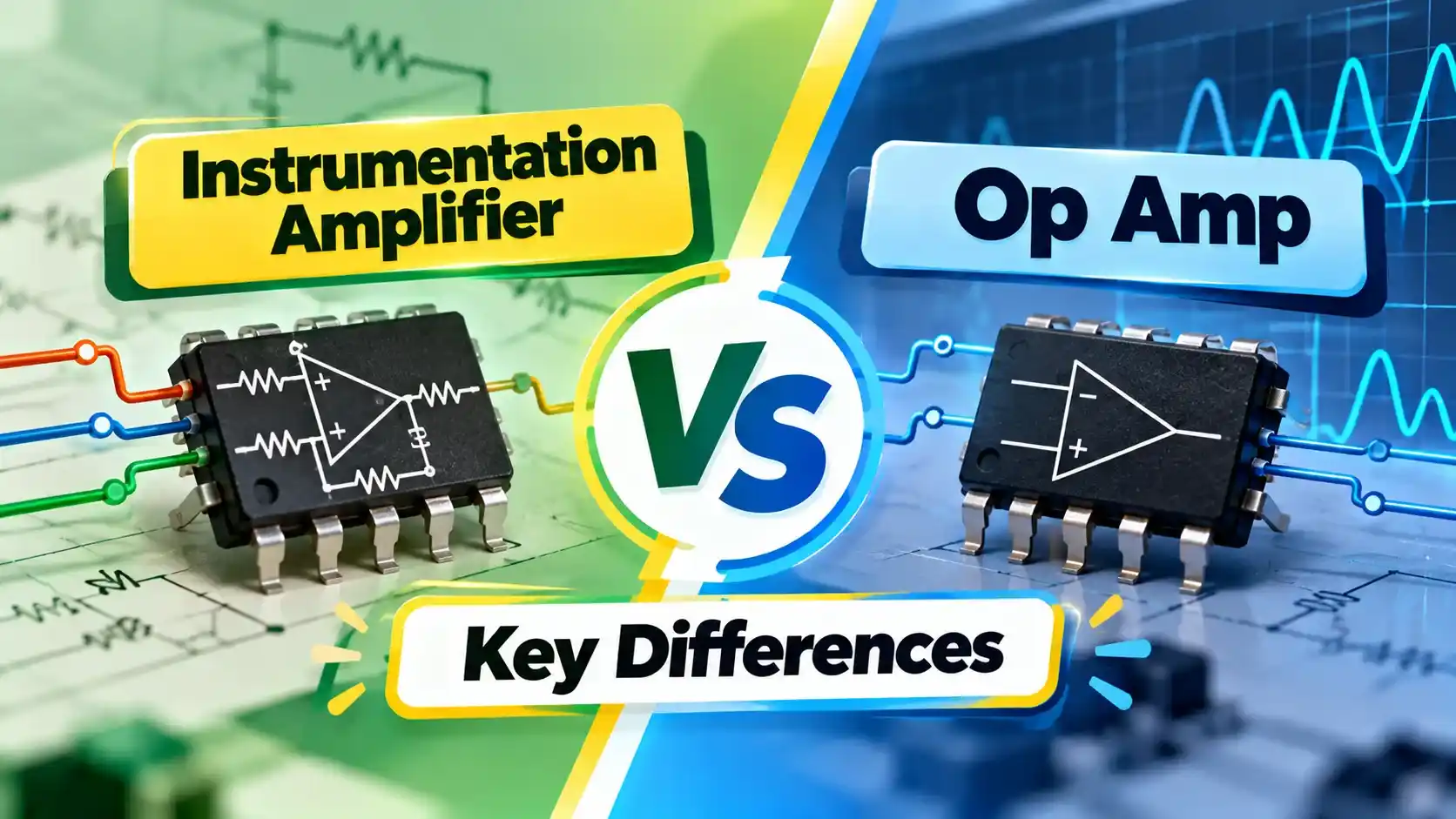
Instrumentation Amplifier vs Op Amp
An operational amplifier is a general purpose gain block, the designer adds external resistors to set gain, bandwidth, and function, whether that function ends up being a difference amplifier, a filter, or a comparator.
An instrumentation amplifier is a specialized chip built from three internal op amps in a fixed topology, with gain set by one or two external resistors and the tricky feedback paths already handled inside the package.
Choosing between the two is really a question of how much internal engineering you want done for you before the signal ever reaches your gain setting resistor.
How a Standard Op Amp Difference Circuit Works
A single op amp wired as a difference amplifier uses four external resistors, and the common mode rejection of that circuit depends entirely on how well matched those four resistors actually are.
Even one percent resistor tolerance limits common mode rejection to roughly forty six decibels, which sounds reasonable until a real sensor signal sits buried under a much larger shared noise voltage.
Input impedance on this simple circuit is also relatively low, often around one hundred kilohms, which can load down a high impedance sensor and quietly distort the very signal being measured.
How an Instrumentation Amplifier Is Built
A three op amp instrumentation amplifier places a buffer stage in front of each input, giving the whole chip very high input impedance, often in the millions of ohms, regardless of the gain setting chosen.
Those buffer stages feed a final difference stage, and because the internal resistor network is laser trimmed at the factory, common mode rejection climbs far higher than a hand matched external resistor network ever achieves.
Gain is set with a single external resistor, so the same chip can serve a wide range of applications just by changing one component value rather than four matched ones.
Key Differences Between the Two
| Property | Op Amp Difference Circuit | Instrumentation Amplifier |
|---|---|---|
| Input impedance | Roughly 100 kiloohms | Millions of ohms |
| Gain setting | Four matched external resistors | One or two external resistors |
| Typical CMRR | Around 46 dB with 1% resistors | 80 to over 100 dB, factory trimmed |
| Component count | One op amp, four resistors | Single packaged chip |
| Best for | General purpose amplification and filtering | Bridge sensors and small differential signals |
When a Plain Op Amp Is the Right Choice
When an Instrumentation Amplifier Is the Right Choice
Common Applications
Common Mistakes When Choosing Between Them
A Real Bridge Sensor Comparison
Take a strain gauge bridge with a rated output of two millivolts per volt of excitation, driven from a ten volt supply, sitting on a chassis that also carries several hundred millivolts of ground noise.
A discrete op amp difference circuit built with one percent resistors would let a meaningful slice of that chassis noise bleed straight into the measurement, since its common mode rejection sits around forty six decibels at best.
A dedicated instrumentation amplifier with one hundred decibels of rejection attenuates that same chassis noise by roughly a factor of one hundred thousand, leaving the twenty millivolt bridge signal essentially undisturbed by comparison.
Over a full measurement range, that difference in rejection is often the entire gap between a reading that tracks a reference scale accurately and one that drifts with every nearby motor or contactor switching nearby.
Bandwidth and Noise Tradeoffs
An instrumentation amplifier's internal buffer stages add a small amount of extra noise and slightly reduce bandwidth compared with a single bare op amp running at the same gain.
For most sensor signal chains, where the signal of interest sits well below one kilohertz, this tradeoff is negligible next to the common mode rejection gained by using a proper instrumentation amplifier.
Fast signal paths, such as a wideband RF stage or a high speed data converter driver, are exactly the case where a plain op amp's higher bandwidth still wins out over an instrumentation amplifier.
Instrumentation Amplifier vs Op Amp: Quick Selection
Plain Op Amp Circuit
Lower cost, flexible for many functions, but common mode rejection is limited by external resistor matching.
Instrumentation Amplifier
Higher cost, single purpose, but delivers far higher input impedance and common mode rejection out of the box.
Many precision sensor front ends use both, an instrumentation amplifier pulls a clean signal off the bridge first, then a plain op amp stage filters or drives the signal onward from there.
Popular Instrumentation Amplifier Chips Worth Knowing
The AD620 remains one of the most widely taught instrumentation amplifier chips, offering a single external resistor for gain from 1 to 10000 and a common mode rejection ratio around 100 decibels at gain of 10.
The INA128 and INA129 family offer similar single resistor gain setting with slightly different bandwidth and noise tradeoffs, often chosen for industrial signal conditioning where board space and part count matter.
Newer zero drift instrumentation amplifiers add internal chopper stabilization, virtually eliminating offset voltage drift over temperature, which matters most in precision weighing and calibration equipment held to a tight accuracy budget.
Reading a Datasheet Before Choosing a Part
Watch: Instrumentation Amplifier Explained
Instrumentation Amplifier vs Op Amp FAQs
Related Articles on This Site
- Operational Amplifier Op Amp Basics
- Wheatstone Bridge: 10 Applications
- Strain Gauge Working Principle
- Bonded and Unbonded Strain Gauges
- Signal Conditioning in Instrumentation
External References
What We Learn Today
- An instrumentation amplifier packages three op amps and a trimmed resistor network into one precision chip.
- Higher input impedance and far better common mode rejection make it the right pick for bridge sensors.
- A plain op amp still wins on cost and flexibility when common mode rejection is not a real concern.