
The mode of a control block decides who owns the setpoint and the output, the operator, the algorithm or another block.
DCS control modes decide who writes the setpoint and who writes the output of a control loop. Knowing them well prevents process bumps, broken cascades and confused operators.
What Are DCS Control Modes?
DCS control modes are the operating states of a control function block, usually a PID block, that define where its setpoint and output come from. They are part of every distributed control system and every FOUNDATION fieldbus device.
An operator changes modes from the faceplate, while the block reports its actual mode back. The difference between the requested and actual mode tells you when something below is not ready.
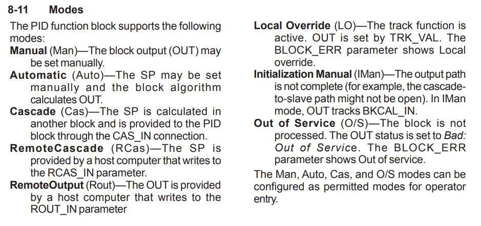
FOUNDATION fieldbus defines a mode parameter with four parts, target, actual, permitted and normal. Most DCS vendors follow the same model even for their own blocks.
Modes connect closely to DCS function block programming, because blocks pass status and back calculation values to each other to manage mode changes.
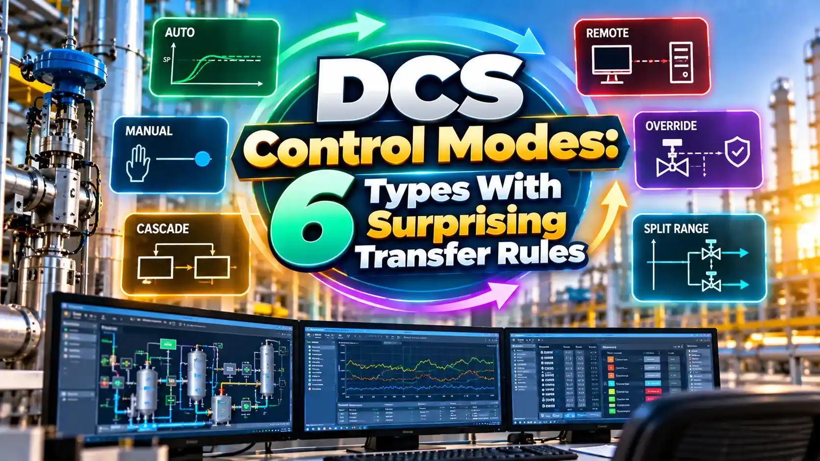
6 Main DCS Control Modes
Operator writes the output directly and the PID algorithm does not move it.
Operator writes the setpoint and PID calculates the output.
Setpoint comes from an upstream block such as a primary controller.
Setpoint is written by an external host or supervisory program.
Output is written directly by an external program.
Block is not executing and its output holds or goes to a safe value.
Two more states appear as actual modes only. IMAN, or initialization manual, shows the downstream path is not ready, and LO, or local override, shows an interlock or local action has taken the output.
Operators cannot choose IMAN or LO. The block enters them by itself and returns to the target mode when the condition clears.
Who Owns the Setpoint and Output
| Mode | Setpoint Written By | Output Written By | PID Active |
|---|---|---|---|
| MAN | Operator, often tracking PV | Operator | No |
| AUTO | Operator | PID algorithm | Yes |
| CAS | Upstream block | PID algorithm | Yes |
| RCAS | External host | PID algorithm | Yes |
| ROUT | Not used | External program | No |
| OOS | Not used | Holds last value | No |
In a cascade control loop, the secondary controller runs in CAS so it follows the primary controller output. The primary runs in AUTO with a setpoint from the operator.
If the secondary is put in MAN, the primary sees the cascade broken and goes to IMAN. This prevents the primary output from winding up while it has no effect.
Bumpless Transfer and Setpoint Tracking
Bumpless transfer means the output does not jump when the mode changes. The block initializes its internal integral term to the current output before the algorithm takes over.
Setpoint tracking helps further by keeping the setpoint equal to PV while in manual. When the loop enters AUTO, the error is zero and the proportional term adds no sudden kick.
In cascade, the secondary sends a back calculation value to the primary. The primary uses it to line up its output so the cascade can close without a bump, a detail often missed during PID tuning.
Mode Change Bump Formula
Applies when switching MAN to AUTO without setpoint tracking,
for a PID with proportional action on error.
Worked example:
Kc = 2.0
SP = 60 percent, PV = 55 percent
Error = 60 minus 55 = 5 percent
Output bump = 2.0 × 5 = 10 percent valve jump
A 10 percent step on a large steam or fuel valve can upset the whole unit. With PV tracking enabled, the error at switchover is zero and the bump disappears.
Some DCS blocks also offer proportional on PV instead of error. That option removes setpoint kicks during normal operation as well.
5 Steps to Close a Cascade Safely
The same order applies to split range and ratio loops that feed a secondary block.
Always close the inner loop first and open the outer loop first. This single rule prevents most cascade upsets during commissioning.
Where DCS Control Modes Are Used
Local override is linked to interlock design. Our article on force vs override explains how these actions should be controlled and logged.
Alarm systems should report unexpected mode changes. Guidance in ISA 18.2 alarm management helps decide which ones deserve an alarm.
Mode Change Bump Calculator
A negative result means the output steps down instead of up. Either way, tracking removes the step completely.
- Setpoint tracking in manual.
- Back calculation in every cascade.
- Normal mode defined for each block.
- Mode changes logged for review.
- Primary winds up when cascade is broken.
- OOS blocks hold outputs unexpectedly.
- ROUT left active after a sequence ends.
- Operators misread IMAN as a fault.
FOUNDATION Fieldbus Tutorial PDF
Cascade Mode Transfer Video
DCS Control Modes FAQ
Related Articles
- What Is Cascade Control
- DCS Control Strategies
- DCS Function Block Programming
- PID Controller Tuning Guide
- FOUNDATION Fieldbus Explained
External References
- DCS Controller Modes, Casual Process Engineer
- FOUNDATION Fieldbus Operational Modes, NI
- FOUNDATION fieldbus Book, Yokogawa
- FF Function Blocks, Control.com Textbook
- PID Controller, Wikipedia
What We Learn Today
- Each mode defines who owns the setpoint and who owns the output.
- Tracking and back calculation make mode changes bumpless.
- In a cascade, close the inner loop first and open the outer loop first.