
A Transformer Vector Group tells you two things at once, how each winding is connected and how far the secondary voltage lags the primary, and reading it wrong can damage two transformers the moment they are paralleled.
A Transformer Vector Group is a short code, such as Dyn11, that describes winding connections and phase displacement in one label. Getting it wrong is one of the fastest ways to damage a transformer during commissioning.
This builds on the same phasor thinking used when reading a Single Line Diagram, since both describe how power actually flows through connected equipment rather than just naming the parts.
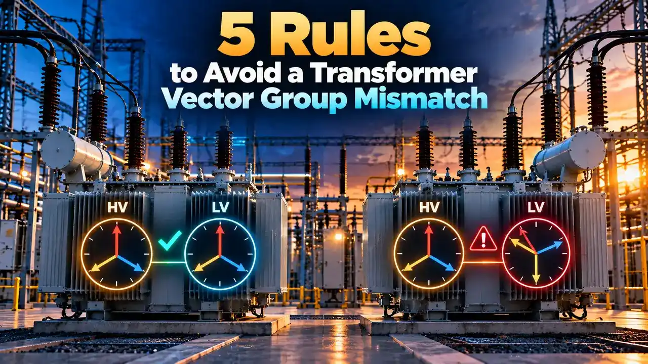
Transformer Vector Group
Every three phase transformer nameplate carries a vector group label, something like Dyn11, Yyn0, or YNd1, and each part of that short code carries real electrical meaning.
The first letter describes the high voltage winding connection, capital D for delta or capital Y for star. The second letter describes the low voltage winding the same way, lowercase this time.
An added lowercase n means the low voltage star point is brought out as a neutral terminal, useful whenever the secondary needs to supply single phase loads or unbalanced current.
The final number is a clock position from zero to eleven, and multiplying that number by thirty degrees gives the exact phase displacement between the primary and secondary voltage.
None of this is arbitrary labeling. Every letter and digit traces back to how the actual coils are wound and connected inside the tank, which is exactly why the code has to be read in order, never guessed from habit.
Manufacturers stamp this code on the nameplate precisely because two transformers with identical voltage and kVA ratings can still be completely incompatible for parallel operation if their internal connections differ.
Utilities and plant engineers treat the vector group as a safety critical piece of data, checked as carefully as voltage ratio and impedance before any transformer is commissioned or connected alongside an existing one.
Testing houses confirm the label rather than trust it, running a polarity and phase sequence check on every new or repaired unit before it ever gets certified for parallel service on site.
5 Steps to Decode a Vector Group Label
Common Transformer Vector Groups
Delta primary, star secondary with neutral, thirty degree lead. The default choice for most distribution transformers.
Star primary, star secondary with neutral, zero phase shift. Simple but sensitive to unbalanced single phase loading.
Delta primary, star secondary with neutral, thirty degree lag instead of lead, common outside India and the UK.
Star primary with neutral, delta secondary, thirty degree lead. Common on generator step up transformers.
The Clock Notation, Visually
The high voltage phasor always sits at the 12 position by convention. Wherever the low voltage phasor points, that clock number becomes the last digit of the vector group.
Reading it this way turns an abstract label into something a technician can actually picture, two hands on a clock face, rather than a string of letters and a number to be memorized without context.
Most software used for protection coordination and short circuit studies asks for this exact clock number directly, so getting comfortable with the conversion pays off well beyond just reading a nameplate.
Converting Clock Number to Degrees
Example, vector group Dyn11:
Clock number = 11
Phase displacement = 11 × 30 = 330 degrees lead
Equivalent to 30 degrees lag, measured the other direction
Example, vector group Yyn0:
Clock number = 0
Phase displacement = 0 × 30 = 0 degrees, primary and secondary in phase
Common Mistakes When Checking Vector Group
Assuming same kVA means compatible: matching voltage ratio and kVA rating says nothing about phase displacement, and both must still be verified separately before paralleling.
Another frequent error is trusting an old drawing instead of the physical nameplate, since a rewound or repaired transformer can quietly end up with a different vector group than its original records show.
Skipping a phase sequence and polarity check before energizing a new transformer alongside an existing one is how a wrong vector group turns into a real fault instead of a paperwork correction.
Star vs Delta vs Zigzag Windings
| Winding | Neutral Available | Handles Unbalanced Load | Typical Use |
|---|---|---|---|
| Star (Y) | Yes, with n suffix | Limited without tertiary winding | Secondary side, distribution |
| Delta (D) | No | Good, absorbs third harmonic current | Primary side, generator step up |
| Zigzag (Z) | Yes | Very good, purpose built for this | Earthing transformers |
Star windings are the natural choice wherever a neutral connection is actually needed downstream, since the star point gives a convenient reference for both grounding and single phase distribution.
Delta windings, lacking a neutral of their own, are chosen instead where harmonic suppression or a closed loop for circulating triplen harmonic current matters more than neutral access.
Zigzag windings exist almost entirely for one purpose, creating an artificial neutral point where none would otherwise exist, most often paired with a delta system that has no accessible star point at all.
Where Each Connection Shows Up
Industrial plants often standardize on one or two vector groups across their entire site, purely to make future expansion and parallel operation predictable instead of case by case guesswork.
A plant with a mix of vector groups inherited from different eras of construction usually needs isolation transformers or careful switching arrangements to keep incompatible systems from ever being tied together by accident.
Star vs Delta on the Primary Winding
Star Primary
Lower insulation stress per winding since each coil only sees phase voltage, useful at higher transmission voltages.
Delta Primary
Naturally suppresses third harmonic current, a common reason it is chosen for generator step up duty.
Vector Group Phase Displacement Calculator
Reference Document
Watch: Transformer Vector Groups Explained with Phasor Diagrams
Transformer Vector Group FAQs
Related Articles on This Site
- Current Transformer Working Principle
- Single Line Diagram Symbols and How to Read One
- Protective Relays Explained
- AC Motors and Generators: How Back EMF Links Them
- Grounding Techniques Explained
External References
- Understanding Vector Group of Transformer, Electrical Engineering Portal
- IEC 60076 Part 1:2011, Power Transformers, General
What We Learn Today
- A Transformer Vector Group encodes both winding connection and phase displacement in one short label.
- The clock number, multiplied by thirty degrees, gives the exact phase shift between primary and secondary.
- Two transformers must share the same phase displacement before they can ever be paralleled safely.