
Nearly every op amp and instrumentation circuit built for measuring a small signal in a noisy environment relies on a differential amplifier at its core.
A differential amplifier amplifies the voltage difference between two input signals while ideally rejecting any voltage the two inputs share in common, a property quantified by its common mode rejection ratio.
This underlying circuit also forms the input stage of nearly every op amp made today, so understanding it here pays off across many other circuits.
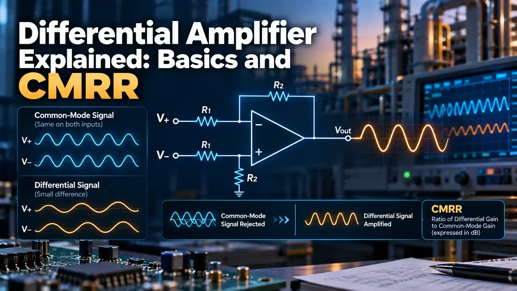
What Is a Differential Amplifier
Two transistors, matched as closely as possible, share a common emitter or source connection tied to a constant current source, with each transistor's base or gate receiving one of the two input signals.
The output is taken as the voltage difference between the two collectors or drains, which swings in proportion to the difference between the two input voltages rather than either input alone.
Because the pair shares a common current source, any voltage that rises or falls identically on both inputs, called the common mode signal, produces almost no change in that output difference.
How the Two Halves Share Current
The shared current source forces the total current through both transistors to stay constant, so when one input rises relative to the other, more current flows through one side and correspondingly less through the other.
This current steering behavior is what converts a voltage difference at the input into an unbalanced current, and eventually an unbalanced voltage, at the two output terminals.
Differential Mode vs Common Mode Signals
A differential mode signal is the part that differs between the two inputs, the actual signal of interest that this circuit is built to amplify with high gain.
A common mode signal is the part shared identically by both inputs, often noise picked up equally by both wires, which a well designed circuit should reject rather than amplify.
Understanding CMRR
| Term | Meaning | Ideal Value |
|---|---|---|
| Differential gain | Amplification of the wanted signal difference | High, set by design |
| Common mode gain | Amplification of the unwanted shared signal | As close to zero as possible |
| CMRR | Differential gain divided by common mode gain | Infinite in the ideal case |
Why Real Circuits Fall Short of Ideal
Perfectly matched transistors and resistors do not exist in practice, and even tiny mismatches between the two halves of the pair let a small fraction of the common mode signal leak into the output.
Using a well matched pair on a single piece of silicon, rather than two separate discrete transistors, dramatically improves matching and therefore CMRR compared to a hand built discrete version.
Input Offset Voltage
Even a well matched pair rarely balances perfectly, leaving a small residual voltage difference at the output when both inputs are tied to exactly the same voltage, known as input offset voltage.
Precision applications sometimes add a trimming network to null this offset, while less demanding designs simply account for it as a known error term in the overall measurement chain.
The Role of the Current Source
Replacing a simple resistor with a proper current source in the shared connection point significantly boosts common mode rejection, since a current source presents very high impedance to any common mode voltage change.
This is why nearly every practical design uses a dedicated current source rather than a plain resistor, even though a resistor is simpler and cheaper to implement.
Common Applications
Why This Matters for Noisy Environments
Long cable runs in an industrial plant pick up electrical noise from nearby motors, VFDs, and switching equipment, and that noise typically couples nearly identically onto both wires of a twisted pair.
A differential amplifier at the receiving end sees that noise as a common mode signal and rejects most of it, recovering the original small signal far more cleanly than a single wire referenced to ground ever could.
This is precisely why instrumentation cabling standards favor twisted, shielded pairs feeding a differential input, rather than a single conductor referenced to a remote ground point.
Differential vs Single Ended Amplifier
This Design
Rejects shared noise between two inputs, needs matched components and more careful design.
Single Ended Stage
Simpler with one input referenced to ground, but offers no common mode rejection at all.
Choosing a differential amplifier over a single ended design almost always comes down to how much noise or ground potential difference exists between the signal source and the amplifier.
Building One From an Op Amp
A single standard op amp with four precisely matched resistors forms a simple subtractor circuit, taking two inputs and producing an output proportional to their difference times a fixed gain set by the resistor ratio.
This configuration is easy to build with off the shelf parts, though its input impedance and CMRR are both limited compared to a dedicated instrumentation amplifier built from multiple internal stages.
For most everyday measurement tasks, this simple four resistor version is perfectly adequate, reserving the more elaborate multi stage instrumentation design for applications demanding very high CMRR and input impedance.
Common Mistakes to Avoid
Measuring CMRR on the Bench
Tying both inputs together and applying a known AC signal to that common point, while measuring the small residual output, gives the common mode gain directly from a bench test setup.
Comparing that measured common mode gain against the separately measured differential gain, taken with a normal differential input signal, yields the practical CMRR figure for the actual physical circuit under test.
Real measured values are almost always lower than a datasheet's typical figure, since production tolerances and PCB layout both introduce extra mismatch beyond the ideal simulated circuit.
Watch: Differential Amplifier Basics and CMRR
Differential Amplifier FAQs
Related Articles on This Site
- Operational Amplifier, Op Amp Basics
- Cascode Amplifier Working Principle
- Transistor Common Emitter Amplifier
- Wheatstone Bridge, 10 Applications
- BJT Currents and Voltages Explained
External References
What We Learn Today
- A differential amplifier amplifies the difference between two inputs while rejecting their shared common signal.
- CMRR quantifies how well the circuit rejects unwanted common mode noise versus the wanted signal.
- A matched transistor pair and a proper current source are essential for achieving high CMRR.