
Bit shift and rotate instructions move bits through a register or array one position at a time. BSL and BSR shift through arrays. ROL and ROR rotate within a single register.
We will understand how each instruction moves bits through registers or arrays, what happens to the bit that falls off the end, and what value enters from the other end.
We will also cover the key differences between shift and rotate instructions, look at bit-state tables for each instruction, and see real application examples in PLC ladder logic programs.
Bit shift and rotate instructions are used in conveyor tracking, step sequencers, and pattern generators where a bit must move through a series of positions in a controlled way.
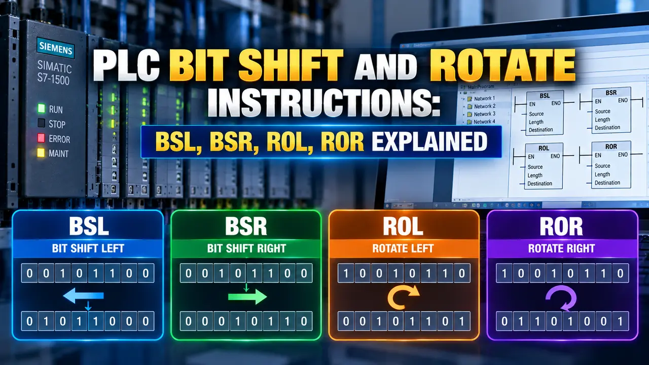
PLC Bit Shift and Rotate Instructions: BSL BSR ROL ROR Overview
Shifts all bits in an array toward the high end. A new bit enters at bit 0 from Source. The exiting bit goes to the UL overflow bit.
Shifts all bits in an array toward the low end. A new bit enters at the top from the Source parameter. The exiting bit goes to the UL overflow bit.
Rotates all bits in a single register one position to the left. The bit exiting the top wraps back to bit 0. No bit is lost. The register content circulates continuously.
Rotates all bits in a single register one position to the right. The bit that shifts out of bit 0 wraps back and re-enters at the top bit. No bit is lost.
BSL: Bit Shift Left Instruction
BSL operates on a bit array. Each rising edge shifts every bit one position left. A new bit enters at bit 0 from Source. The exiting bit goes to the UL bit.
| State | Bit 0 | Bit 1 | Bit 2 | Bit 3 | UL (overflow) |
|---|---|---|---|---|---|
| Before shift | 1 | 0 | 1 | 1 | 0 |
| Source bit = 0 | |||||
| After BSL | 0 | 1 | 0 | 1 | 1 |
The original bit 3 (value 1) moved into the overflow (UL) bit. Source bit value 0 entered at bit 0. Every other bit moved one step to the left.
BSR: Bit Shift Right Instruction
BSR mirrors BSL. Each rising edge shifts all bits toward lower bit numbers. A new bit enters at the highest position. The exiting bit 0 goes to the UL bit.
| State | Bit 3 | Bit 2 | Bit 1 | Bit 0 | UL (overflow) |
|---|---|---|---|---|---|
| Before shift | 1 | 0 | 1 | 0 | 0 |
| Source bit = 1 | |||||
| After BSR | 1 | 1 | 0 | 1 | 0 |
Source bit value 1 entered at bit 3. Every other bit moved one step to the right. The original bit 0 (value 0) moved into the UL overflow bit.
ROL and ROR: Rotate Instructions
ROL and ROR operate on a single register, not an array. The bit exiting one end re-enters from the other. No bit is ever lost.
| Instruction | Bit 3 | Bit 2 | Bit 1 | Bit 0 | What happened |
|---|---|---|---|---|---|
| Before rotate | 1 | 0 | 0 | 0 | |
| After ROL | 0 | 0 | 0 | 1 | Bit 3 wrapped to bit 0 |
| After ROR | 0 | 1 | 0 | 0 | Bit 0 would wrap to bit 3 (from original) |
BSL vs BSR vs ROL vs ROR: Full Comparison
| Feature | BSL | BSR | ROL | ROR |
|---|---|---|---|---|
| Direction | Left (toward high bit) | Right (toward low bit) | Left (wraps) | Right (wraps) |
| Operates on | Bit array (multi-word) | Bit array (multi-word) | Single register | Single register |
| New bit source | Source parameter (external bit) | Source parameter (external bit) | Exiting bit (wraps back) | Exiting bit (wraps back) |
| Exiting bit | Captured in UL overflow bit | Captured in UL overflow bit | Re-enters at bit 0 | Re-enters at top bit |
| Bits lost? | Yes (exits to UL then gone) | Yes (exits to UL then gone) | No | No |
| Executes on | Rising edge only | Rising edge only | Rising edge only | Rising edge only |
| Typical use | Conveyor tracking, FIFO sequencing | Conveyor tracking (reverse), LIFO sequencing | Circular step sequencer, rotating lamp pattern | Circular step sequencer (reverse), rotating pattern |
Real Applications of Bit Shift and Rotate in PLC Programs
Watch: PLC Bit Shift Instructions Explained
PLC Bit Shift and Rotate Questions Engineers Ask
Related Articles on This Site
- PLC Math Instructions Explained
- PLC Compare Instructions Explained
- PLC Memory Addressing Explained
- 9 PLC Data Types Explained
- Ladder Logic for Beginners
External References
- Logix5000 General Instructions Reference Manual | Rockwell Automation
- PLC Bit Shift Instructions | PLC Academy
What We Learn Today
- BSL shifts bits left through an array on each rising edge. A new bit enters at bit 0 from the Source parameter. The bit that exits the top is captured in the UL overflow bit. BSR does the same in the opposite direction. Both instructions operate across a multi-word array and the exiting bit is permanently lost after the next shift.
- ROL rotates bits left within a single register. The bit that exits the top re-enters at bit 0, so no bit is ever lost. ROR does the same in the opposite direction. After enough rotations equal to the register width, the original pattern is restored.
- Use BSL or BSR for conveyor part tracking, FIFO buffer management, and data serialisation where bits travel through an array and exit at the end. Use ROL or ROR for circular step sequencers and rotating output patterns where the same set of bits must circulate continuously.