
A DP flow transmitter converts a differential pressure signal from an orifice plate, flow nozzle, or Venturi tube into a flow rate output.
Calibrating it correctly requires understanding two separate outputs: the raw DP in mbar or inH₂O, and the derived flow rate in engineering units.
This guide covers the complete 5-point DP flow transmitter calibration procedure, the square root relationship between DP and flow, as-found and as-left recording, and a 5-point error calculator.
The critical difference in a DP flow transmitter calibration is the square root relationship.
Flow is proportional to the square root of DP, not to DP directly. A 1% DP error produces only a 0.5% flow error.
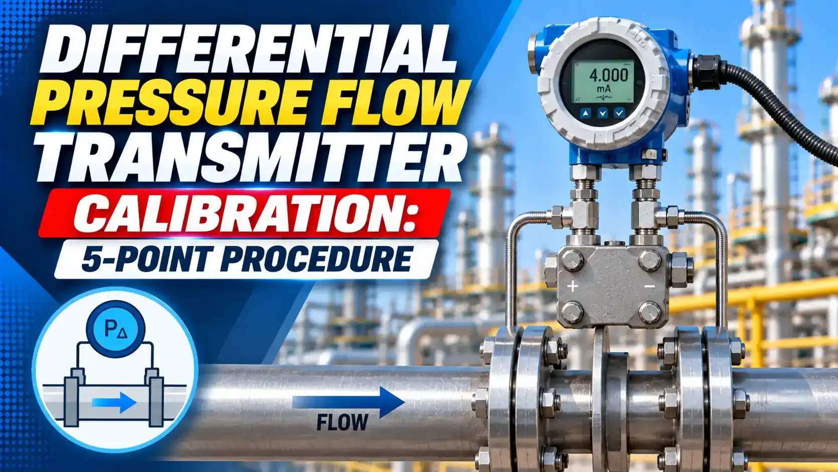
DP Flow Transmitter: What You Are Actually Calibrating
A DP flow transmitter contains two functional blocks that must both be calibrated.
The first block is the DP measurement section: it converts differential pressure into a raw DP value in mbar, inH₂O, or kPa.
The second block is the square root extractor: it converts raw DP into a 4-20 mA flow output using Q ∝ √ΔP.
Q_max: maximum flow rate (at DP_max, corresponding to 20 mA output)
ΔP: measured differential pressure
ΔP_max: maximum DP (calibrated span, corresponding to 100% flow)
Output current: I = 4 + 16 × √(ΔP / ΔP_max)
Example: ΔP_max = 250 mbar. At ΔP = 100 mbar:
I = 4 + 16 × √(100/250) = 4 + 16 × 0.632 = 14.11 mA
This corresponds to 63.2% of maximum flow — not 40% (which would be the linear value).
At 10% of maximum flow, the DP is only 1% of the maximum DP. A transmitter with a DP accuracy of ±0.075% of span produces a flow error of approximately ±0.75% of span at 10% flow.
This is why most DP flow loops have a low-flow cutoff (typically at 10 to 25% of maximum flow) below which the flow reading is forced to zero. Without this cutoff, noise in the DP signal becomes noise in the square root output, producing wildly oscillating low-flow readings.
Before You Start: Calibration Equipment and Checks
A DP flow transmitter calibration requires a calibrated DP source, a reference DP standard (digital indicator, ±0.025% accuracy), and a calibrated mA meter or loop calibrator.
Before applying any pressure, complete these pre-calibration checks.
Connect the HART communicator and read the configured DP span. If the transmitter is ranged for 250 mbar but the primary element was sized for a 500 mbar span, every calibration point will be applied at the wrong DP input.
Confirm the span against the instrument data sheet before proceeding.
Some DP transmitters have the square root extraction disabled — they output a linear 4-20 mA proportional to DP, with the square root done externally in the DCS or flow computer.
Calibrate the transmitter in the mode it actually operates in. If the square root is in the DCS, calibrate the transmitter as a linear DP device (like a pressure transmitter) and verify the DCS output separately.
5-Point DP Flow Transmitter Calibration Procedure
Expected mA at Each Calibration Point
25% DP: 8.00 mA
50% DP: 12.00 mA
75% DP: 16.00 mA
100% DP: 20.00 mA
25% DP: 4 + 16 × √0.25 = 4 + 8.00 = 12.00 mA (50% flow)
50% DP: 4 + 16 × √0.50 = 4 + 11.31 = 15.31 mA (70.7% flow)
75% DP: 4 + 16 × √0.75 = 4 + 13.86 = 17.86 mA (86.6% flow)
100% DP: 20.00 mA (100% flow)
A HART communicator can display both values simultaneously. This lets you verify the square root extraction in the transmitter without needing to calculate it manually.
If the SV (raw DP) reads correctly but the PV (flow output) does not match the expected √DP value, the square root extraction setting or the DP span configuration is incorrect in the transmitter — not a sensor error.
5-Point Error Calculator
Watch: How to Calibrate a DP Flow Transmitter
Calibration Questions
External References
- DP Flow Measurement: Transmitter Selection and Calibration | Emerson Rosemount
- How to Calibrate a DP Flow Transmitter | Yokogawa (2025)
What We Learn Today
- A DP flow transmitter outputs 4-20 mA proportional to √DP (not DP). At 25% DP, the expected output in square root mode is 12.00 mA — not 8.00 mA.
- Always confirm whether the square root extraction is internal (in the transmitter) or external (in the DCS/flow computer) before calibrating. The expected mA values at each point are completely different.
- Apply a low-flow cutoff (typically 10 to 25% of maximum flow) to prevent DP noise from being amplified by the square root function at low flows.