
A temperature transmitter configuration must cover means setting the sensor type, LRV, URV, damping, failure mode, and HART address.
Getting any one of these wrong produces a transmitter that passes loop checks but gives incorrect readings in service.
This guide covers the complete configuration sequence for a 2-wire HART temperature transmitter, from sensor wiring to range entry and output verification.
A temperature transmitter outputs 4 mA at the lower range value (LRV) and 20 mA at the upper range value (URV). Re-ranging sets new LRV and URV values. Calibration corrects actual measurement errors. These two tasks are not the same.
Temperature Transmitter Configuration Parameters Explained
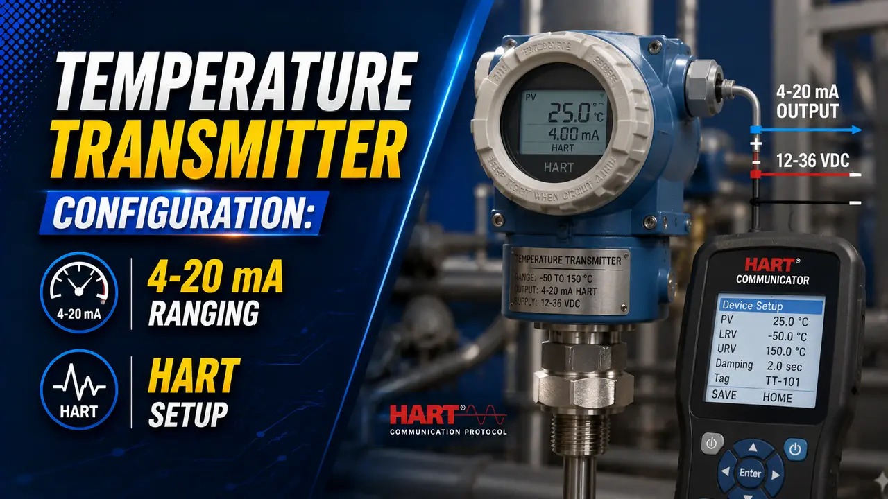
Before a temperature transmitter will give correct readings, it must know the sensor type, the temperature range for 4 mA and 20 mA, and the sensor failure behaviour.
These temperature transmitter parameters are stored in non-volatile memory and changed via a HART communicator or configuration software.
Three concepts are critical to understand before starting configuration: the difference between re-ranging and calibration, what the HART 250-ohm resistor is for, and the meaning of sensor trim vs output trim. Click any term to expand.
Step-by-Step Temperature Transmitter Configuration
4-20 mA Output Calculation for a Given Temperature
T: actual temperature at the sensor
LRV: configured lower range value (temperature at 4 mA)
URV: configured upper range value (temperature at 20 mA)
Example: LRV = 0°C, URV = 300°C, T = 150°C
I = 4 + 16 × (150 minus 0) / (300 minus 0) = 4 + 16 × 0.5 = 12 mA
This temperature transmitter output formula also works in reverse: if you measure the loop current, you can calculate the temperature the transmitter is reporting. See the 4-20 mA signal guide for why this current signal is preferred over voltage signals in industrial settings.
Temperature Transmitter 4-20 mA Calculator
Key Parameters in Temperature Transmitter Configuration
| Parameter | What to Set | Notes |
|---|---|---|
| Sensor type | RTD Pt100, Pt1000, thermocouple J, K, T, E, N, S, R, B, or mV | Must match the physical sensor. Wrong selection gives incorrect linearisation. |
| Sensor wiring | 2-wire, 3-wire, or 4-wire (RTD only) | 3-wire compensates for lead resistance. 4-wire gives highest accuracy. 2-wire RTD introduces lead resistance error. |
| LRV (Lower Range Value) | Temperature at 4 mA output | Must be within the sensor type limits. Can be negative for below-zero applications. |
| URV (Upper Range Value) | Temperature at 20 mA output | Span = URV minus LRV. Must exceed minimum span (typically 10 to 25°C for Pt100). |
| Damping | Filter time constant in seconds (0 to 32 seconds typical) | Higher damping reduces noise but slows response. Default 0 to 2 seconds for most applications. |
| Burnout direction | Up (21.5 mA) or down (3.6 mA) on sensor failure | Set based on the safe failure action required by the process. Drives the controller to the safe side. |
| Tag number | Instrument tag from the P&ID (e.g., TT-101) | Stored in HART memory. Displayed by the communicator for identification. |
| HART poll address | 0 for point-to-point (fixed 4-20 mA), 1 to 63 for multidrop | Multidrop mode fixes output at 4 mA. Use only where digital HART data replaces the analog signal. |
| Units | °C, °F, or K | Must match the DCS scaling. Mixing units causes a systematic scaling error across the full range. |
Watch: How to Set Range in a Temperature Transmitter Using HART
Temperature Transmitter Configuration FAQs
External References
- HART Temperature Transmitter: Configuration and 4-20 mA vs HART Guide -- Microcybers (2026)
- How to Calibrate a Temperature Transmitter With HART Communicator -- Megatek (2026)
What We Learn Today
- Re-ranging sets the LRV (4 mA) and URV (20 mA) in transmitter memory. Calibration (sensor and output trim) corrects actual measurement errors. They are different tasks.
- HART requires at least 250 ohms of loop resistance between the communicator connection and the power supply. Check before connecting.
- Configuration sequence: sensor type, sensor wiring, LRV, URV, damping, burnout direction, tag number, units. Verify output with the formula I = 4 + 16 × (T minus LRV) / (URV minus LRV).
- Burnout direction must match the safe failure action required by the process. Set burnout down (3.6 mA) where a low reading drives the controller to a safe state.
- HART poll address 0 = point-to-point mode with active 4-20 mA. Addresses 1 to 63 = multidrop mode with fixed 4 mA analog output.
- Selecting the wrong sensor type causes incorrect linearisation across the full range. Always verify the sensor type entry against the physical sensor connected.